Description of I/O extension modules
3827_en_B PHOENIX CONTACT 29/138
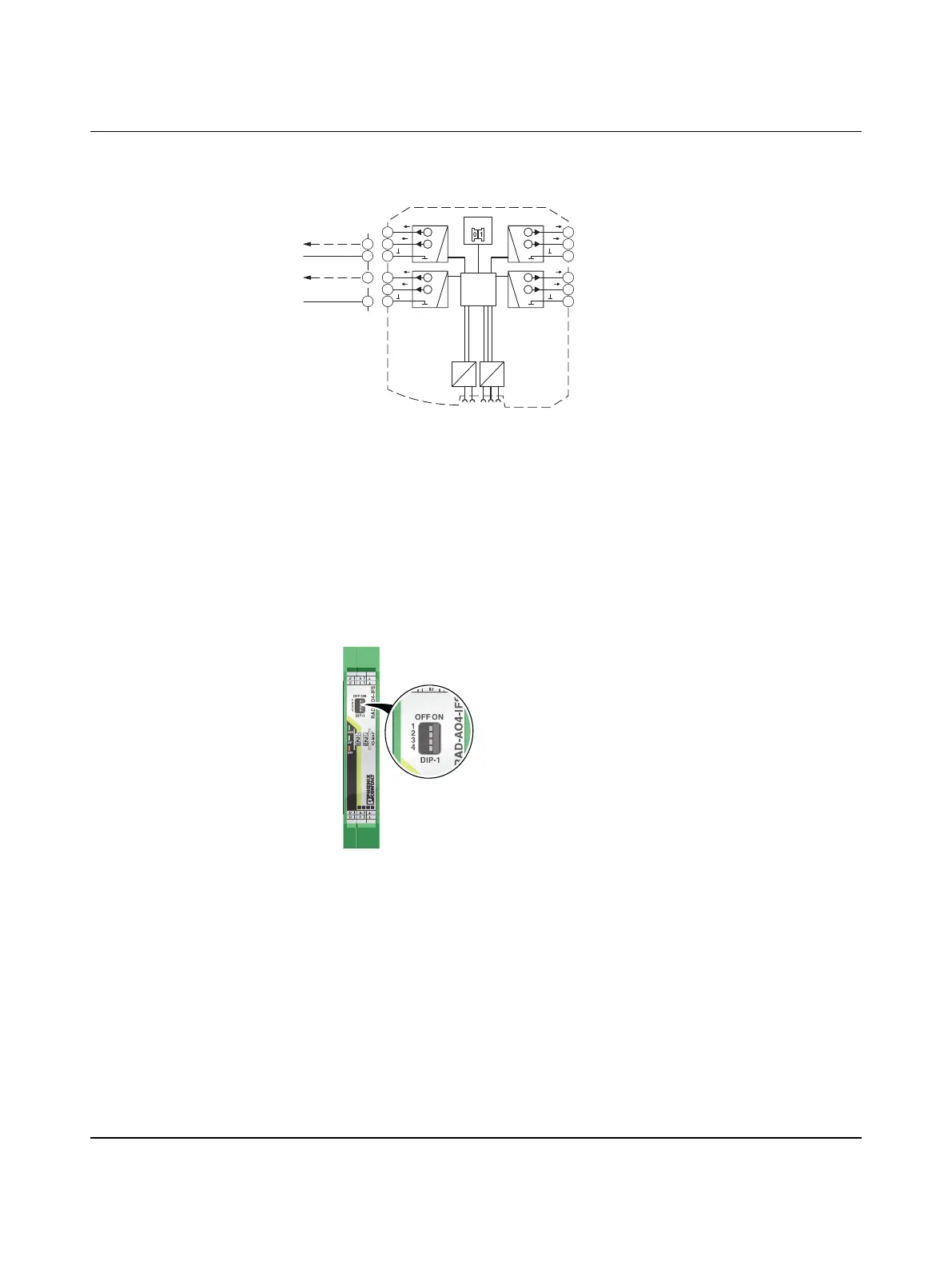
3.3.2 Basic circuit diagram
Figure 3-18 Basic circuit diagram for the RAD-AO4-IFS
3.3.3 Setting the DIP switches
You can use the DIP switches on the front to set the behavior of the outputs in the event of
an error (e.g., interruption of the wireless connection). Any changes in the setting of the DIP
switches will be directly applied.
– RESET = Output value is set to 0
– HOLD = Hold last valid output value
Figure 3-19 DIP switches of the RAD-AO4-IFS
IO-MAP
µC
DC
DC
IFS
IFS
4.1
U
4.2
I
4.3
U
4
I
4
4
5.1
U
5.2
I
5.3
U
3
I
3
3
3.1
U
3.2
I
3.3
U
2
I
2
2
2.1
U
2.2
I
2.3
U
1
I
1
1
3.2
3.3
GND
2.1
2.3
GND
0...10V DC
0/4...20 mA
3
4U4
U3
I4
I3
1
2U2
U1
I2
I1
OFF ON
DIP-1
1
2
3
4
PWR
DAT
ERR
444
3
3
222
11

 Loading...