Description of I/O extension modules
3827_en_B PHOENIX CONTACT 39/138
CNT LED
The green CNT LED indicates that pulse counter mode is activated.
DI1 ... DI8
The yellow DI1 ... DI8 LEDs indicate the status of the digital inputs.
In pulse counter mode: The DI1 and DI7 LEDs flash in time with the recorded pulses. The
DI3 and DI5 LEDs light up when the counter state is reset.
3.5.6 Setting the I/O-MAP address
Use the thumbwheel to set the I/O-MAP address. The extension module in the Radioline
wireless system is addressed using the I/O-MAP address. You can assign a maximum of
01 ... 99 addresses to the I/O extension modules in the entire wireless network.
OFF No error
Flashing Mode switched using DIP switch 1, but not yet applied
ON Pulse counter mode of digital inputs DI1 and DI7
DI3 ON (0.5 second) Counter state DI1 reset to 0
DI5 ON (0.5 second) Counter state DI7 reset to 0
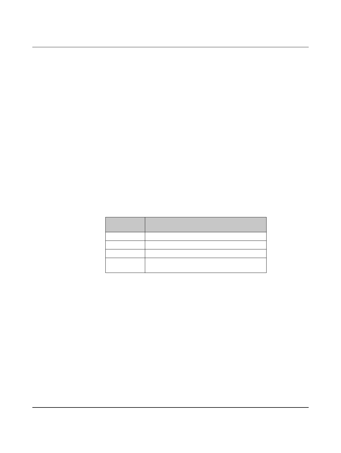
Table 3-9 Setting the I/O-MAP address for the RAD-DI8-IFS
Thumbwheel
setting
Description
01 ... 99 I/O-MAP address
00 Delivery state
**, 1* ... 9* Setting not permitted
*1 ... *9 Interface System slave address, for use with other
Interface System (IFS) master devices

 Loading...