Description of I/O extension modules
3827_en_B PHOENIX CONTACT 25/138
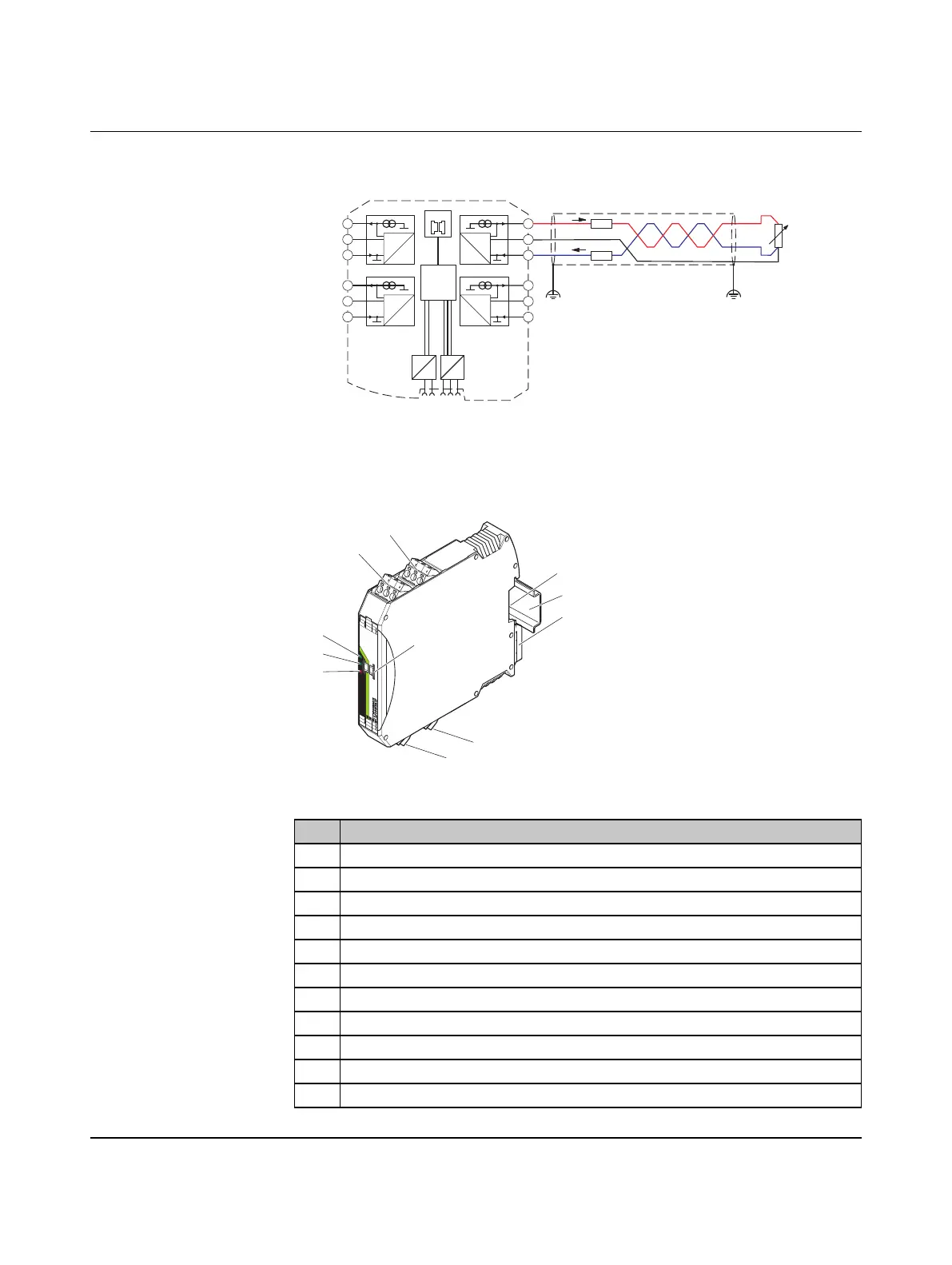
3-wire connection technology with twisted pair cables and shielding
Figure 3-13 3-wire connection technology with twisted pair cables and shielding
3.2.4 Structure
Figure 3-14 RAD-PT100-4-IFS structure
Item Designation
1 Pt 100 input 2 for 2- and 3-wire sensors
2 Pt 100 input 1 for 2- and 3-wire sensors
3 White thumbwheel for setting the I/O-MAP address
4 Connection option for DIN rail connector
5 DIN rail
6 Metal foot catch for DIN rail fixing
7 Pt 100 input 3 for 2- and 3-wire sensors
8 Pt 100 input 4 for 2- and 3-wire sensors
9 ERR status LED, red (communication error)
10 DAT status LED, green (bus communication)
11 PWR status LED, green (supply voltage)
µC
2.1
2.2
2.3
3.1
3.2
3.3
5.1
5.2
5.3
4.1
4.2
4.3
IO-MAP
0
1
DC
DC
IFS
IFS
A
D
1mA
A
D
1mA
A
D
1mA
A
D
1mA
-I2
-U2
+I2
+I1
-U1
-I1
+I3
-U3
-I3
+I4
-U4
-I4
RL
RL
I+
I–
U–
RTD
ϑ
IO-MAP
RAD-PT100-4-IFS
PW
R
D
AT
ER
R
8
8
+
I
1
+
I
2
-
U
1
-
U
2
-I
1
-
I
2
I
3
I
4
-
U
3
-
U
4
-
I
3
-
I
4
+
I
1
+
I
2
-
U
1
-U
2
-
I
1
-
I
2
1
2
3
4
6
8
11
10
9
7
5

 Loading...