Diagnostics on the wireless module
3827_en_B PHOENIX CONTACT 127/138
RSSI LED bar graph
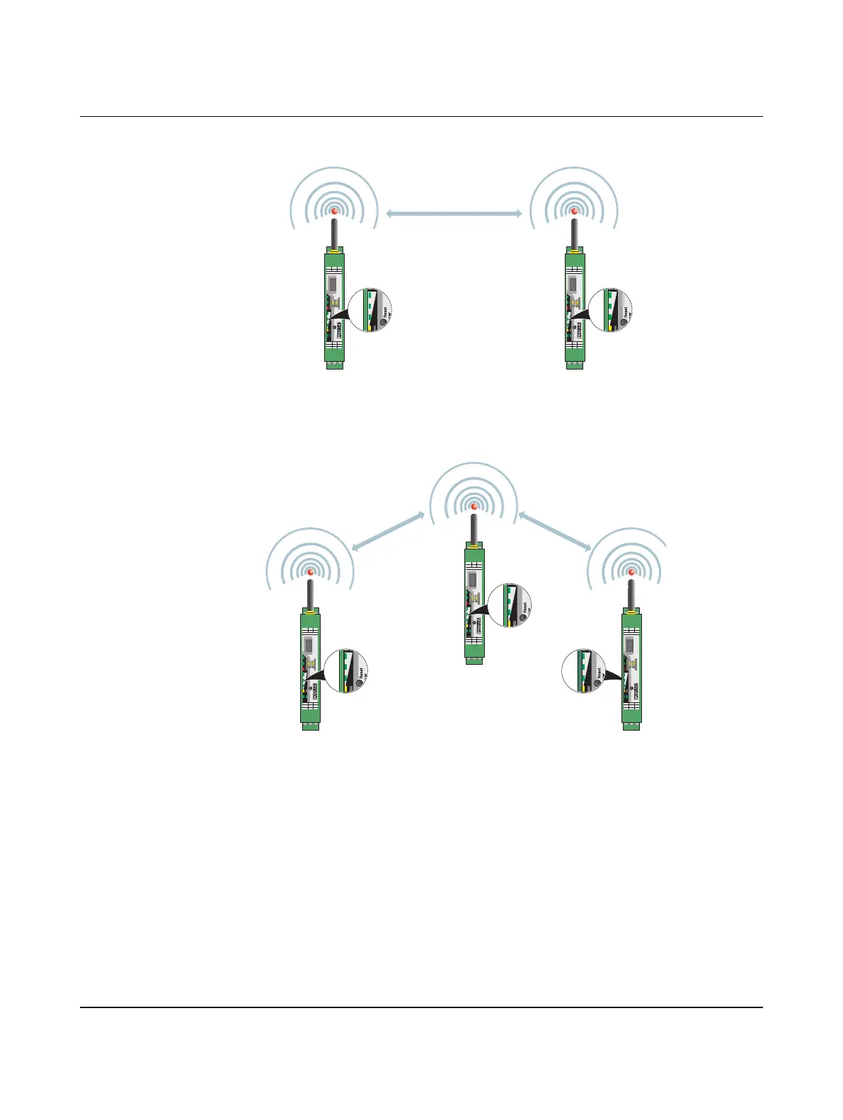
Figure 11-2 Bar graph for point-to-point connection
In a point-to-point connection with only two wireless modules, the LED bar graph is active
on both the master and repeater/slave.
Figure 11-3 Bar graph for point-to-multipoint connection
In a wireless network with more than one repeater/slave, only the yellow LED on the master
is permanently on. The signal strength is displayed on the repeaters/slaves. The signal
strength indicated is always that of the next wireless module in the direction of the master
(parents).
Read the RSSI values via the serial interface of the master wireless module using Modbus
RTU commands (see “Modbus memory map” on page 100).
Master
Repeater /
Slave
RAD-2400-IFS
RAD-ID
Reset
+24 V
0 V
RSSI-
RSSI+
ANT
SPORT
0 1
Pwr
Dat
Err
RXTX
D(A) D(B)
GND
RX
CO
1
NC
1
CO
2
TX
RAD-2400-IFS
RAD-ID
Reset
+24 V
0 V
RSSI-
RSSI+
ANT
SPORT
0 1
Pwr
Dat
Err
RXTX
D(A) D(B)
GND
RX
CO
1
NC
1
CO
2
TX
Master
Repeater /
Slave
Repeater /
Slave
RAD-2400-IFS
RAD-ID
Reset
+24 V
0 V
RSSI-
RSSI+
ANT
SPORT
0 2
Pwr
Dat
Err
RXTX
D(A) D(B)
GND
RX
CO
1
NC
1
CO
2
TX
RAD-2400-IFS
RAD-ID
Reset
+24 V
0 V
RSSI-
RSSI+
ANT
SPORT
0 1
Pwr
Dat
Err
RXTX
D(A) D(B)
GND
RX
CO
1
NC
1
CO
2
TX
RAD-2400-IFS
RAD-ID
Reset
+24 V
0 V
RSSI-
RSSI+
ANT
SPORT
0 3
Pwr
Dat
Err
RXTX
D(A) D(B)
GND
RX
CO
1
NC
1
CO
2
TX

 Loading...