Previous Page Table of Contents Section Contents
Back
Index Next Page
LIFEPAK 500 automated external defibrillator Replacement Procedures
11-40
Replacing Main PCB—Monophasic AED Page 3 of 3
10. If not already present, install the new high voltage shield and two new rivets
from the Main PCB Installation Kit onto the replacement Main PCB.
11. Connect the five spade-lugs P1, P2, P4, P5, and P14 to J1, J2, J4, J5, and
J14 of the replacement Main PCB.
Note: It is critical that the wire connected to J5 on the Main PCB is oriented so
that it exits the PCB and routes directly down toward the lower case cavity. It is
important that the wire does not loop back onto or near the PCB itself.
12. Connect P12 of the power cable to J12 of the replacement Main PCB.
13. Connect P3 of the serial cable to J3 of the replacement Main PCB.
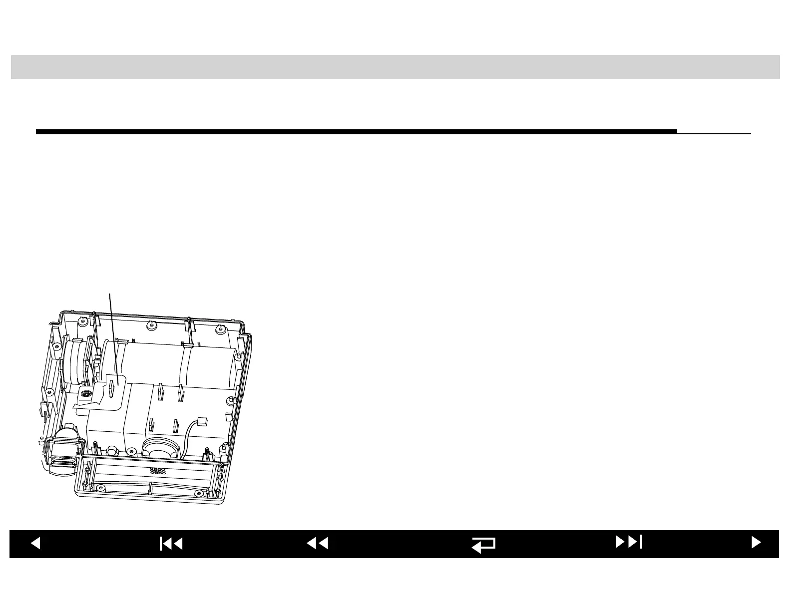
14. Install the wire harness shield as shown at the left.
15. Reposition the Main PCB over the four lower case PCB mounts.
16. Connect P9 of the speaker cable to J9 of the replacement Main PCB.
17. Install the replacement Main PCB onto the four PCB mounts.
After you have installed the replacement Main PCB, jump to the Reassembling
Case procedure.
Wire Harness
Shield