Previous Page Table of Contents Section Contents
Back
Index Next Page
LIFEPAK 500 automated external defibrillator Replacement Procedures
11-48
Installing Main PCB—Biphasic AED
Application The following procedure describes the reinstallation of a Main PCB that was
removed to gain access to other AED assemblies. For installation of a new Main
PCB assembly, follow the Replacing Main PCB—Biphasic AED procedure.
To install the Main PCB:
1. Connect P16 to J16 of the Main PCB. Connect P11 of the data cable to J11
of the Main PCB. Connect the five spade-lugs P2, P4, P13, P15, and P19 to
J2, J4, J13, J15, and J19, respectively, of the Main PCB.
2. Connect P12 of the power cable to J12 of the Main PCB.
3. Connect P3 of the serial cable to J3 of the replacement Main PCB.
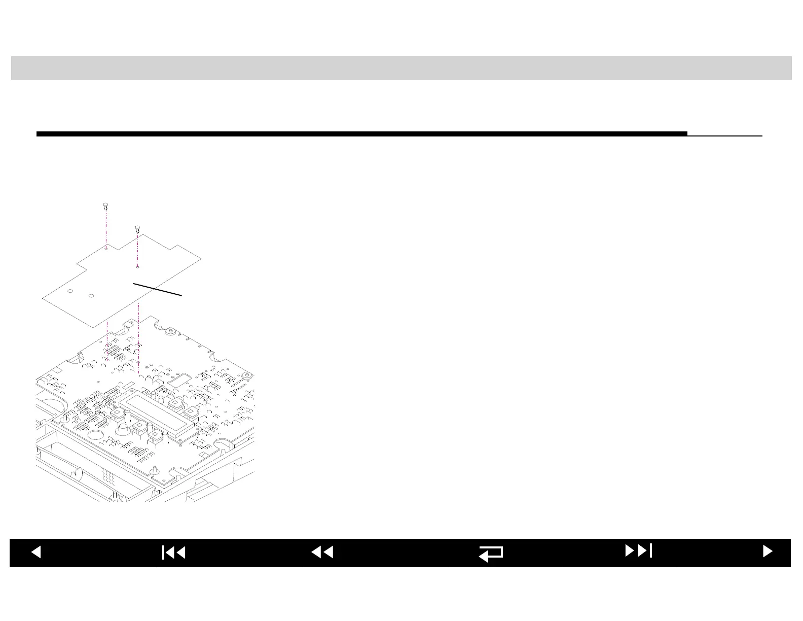
4. Install the Main PCB shield as shown at the left.
5. Reposition the Main PCB over the four lower case PCB mounts.
6. Connect P9 of the speaker cable to J9 of the Main PCB.
7. LIFEPAK 500 Biphasic AED equipped with Readiness Display only: Connect
P20 of the Readiness Display cable to J20 of the Main PCB.
8. Install the Main PCB onto the four PCB mounts.
After you have installed the Main PCB, jump to the Reassembling Case
procedure.
Main PCB
Shield