8
9926595 R01 - 2015-2016 RANGER EV Service Manual
© Copyright Polaris Industries Inc.
8.7
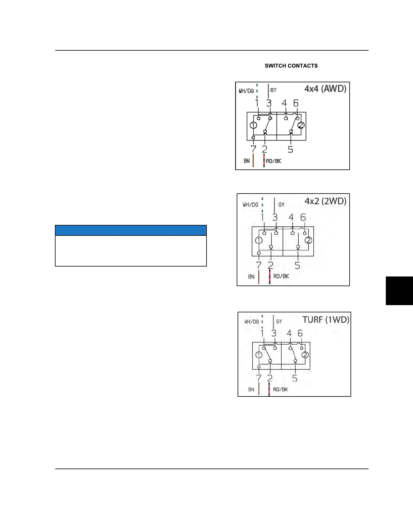
AWD (4x4): Power switched to terminal 3 (GY wire) is
connected through Pin 13 of the Chassis to Dash
harness connector to the AWD GY splice to the front hub
coil connector under the hood. If the BN/WH wire (to Pin
2 of the VCIM) is connected to ground by the module,
AWD is engaged.
2WD (4x2): No power flow through AWD switch.
TURF (1 WD): Power switched to terminal 1 (WH/GN
wire) is connected through Pin 12 of the Chassis to Dash
harness connector to Pin 7 of the VCIM. The VCIM then
controls the activation of the TURF solenoid driver on the
dark green (DG) wire to activate the differential solenoid
and disengage the differential hub.
AWD Switch Testing
1. Open hood. Reach under the dash and press tab on
AWD switch connector to disconnect wire harness
from switch. Do not pull on wiring.
2. Verify power is reaching the switch as described
above.
3. Inspect switch connector pins and sockets and verify
switch continuity in the various positions. (See AWD /
2WD / Turf Switch Contacts, page 8.32.)
NOTE
Disconnect the Main Power Connector (see chapter 1)
before disconnecting any electrical component. The
Main Power Connector is the first to disconnect and the
last to connect when servicing the electrical system.
DIRECTION SELECTOR SWITCH (F / N / R)
VOLTAGE LEVEL: 14.0 VDC
LOCATION: On Dashboard.
ELECTRICAL
 Loading...