8.8
9926595 R01 - 2015-2016 RANGER EV Service Manual
© Copyright Polaris Industries Inc.
SYSTEM WIRING DIAGRAM REFERENCE: See
Direction Selector - System Wiring Diagram, page 8.33.
OVERVIEW: The direction selector switch completes a
ground connection to either the Forward (DB/RD),
Neutral (DG/WH), or Reverse (VT) circuit wires. The
ground is sensed by the controller to determine output to
the drive motor.
The completed ground at the switch also turns on the
appropriate indicator light on the indicator light panel.
(See Direction Selector - System Wiring Diagram, page
8.33)
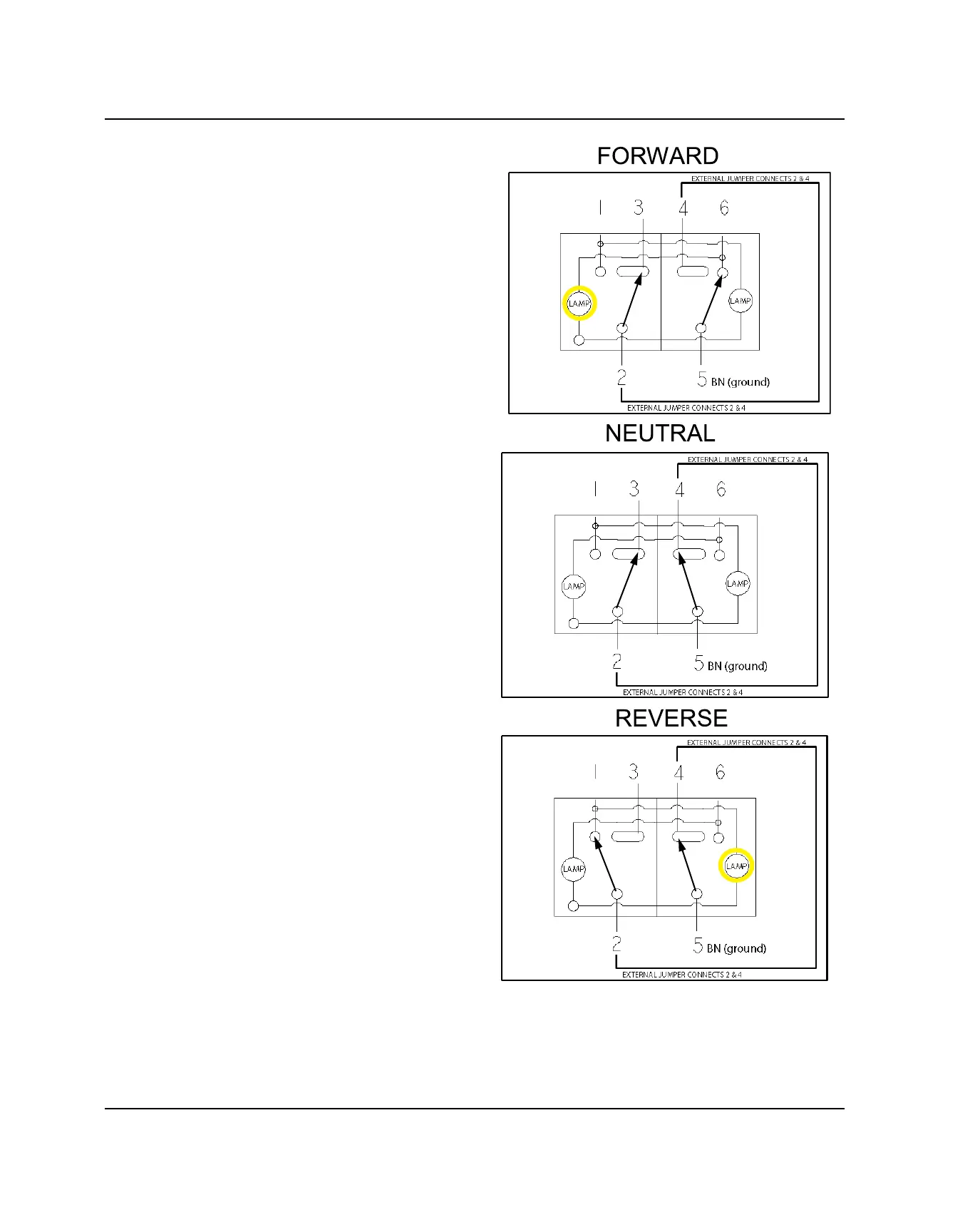
Direction Selector Switch Testing
1. Open hood. Reach under the dash and press tab on
switch connector to disconnect wire harness from
switch. Do not pull on wiring.
2. Inspect switch connections and verify switch
continuity in the various positions as shown below or
see Direction Selector Switch Contacts, page 8.34.
DRIVE MODE SWITCH (HIGH, MAX RANGE,
LOW)
VOLTAGE LEVEL: 14.0 VDC
ELECTRICAL
 Loading...