MAX™ Operator Manual
©
Original Printed In English
Your Sharp Bagger has been shipped to you well crat-
ed in order to prevent any damage to the machine. It
is important that you follow the Uncrating Instructions
attached to crate.
After being uncrated, place the Sharp MAX™ bagger
in well ventilated area, on a rigid and vibration free
surface. Before continuing with the installation of the
machine, ensure all nuts, bolts and screws are tight-
ened as they can come loose during shipping.
The Sharp MAX™ should be placed on a smooth lev-
el surface with access to 100 PSI of clean, dry com-
pressed air, and 115 VAC, 50/60 Hz, 10 Amp
(minimum) properly grounded electrical outlet.
Locate the machine so there is adequate access to
the back side for loading bag film.
Make sure unit is located at a comfortable height for
operation and product loading. See Height Adjust-
ment (page 2-6).
The unit is equipped with two swivel locking casters
for easy maneuverability. Lock the casters after plac-
ing machine in desired location.
ELECTRICAL*
The Sharp MAX™ is equipped with a 3-prong electri-
cal plug for standard, properly grounded, 115 VAC,
50/60 Hz, 10 Amp (minimum) service.
1. Before plugging the cord into the back of the ma-
chine, depress the Emergency Stop Button on the
front of the control panel. See Figure 1-3A.
2. Make sure wall outlet or electrical drop is rated for
proper voltage and that the outlet is grounded.
3. Plug provided power cord into wall outlet or elec-
trical drop.
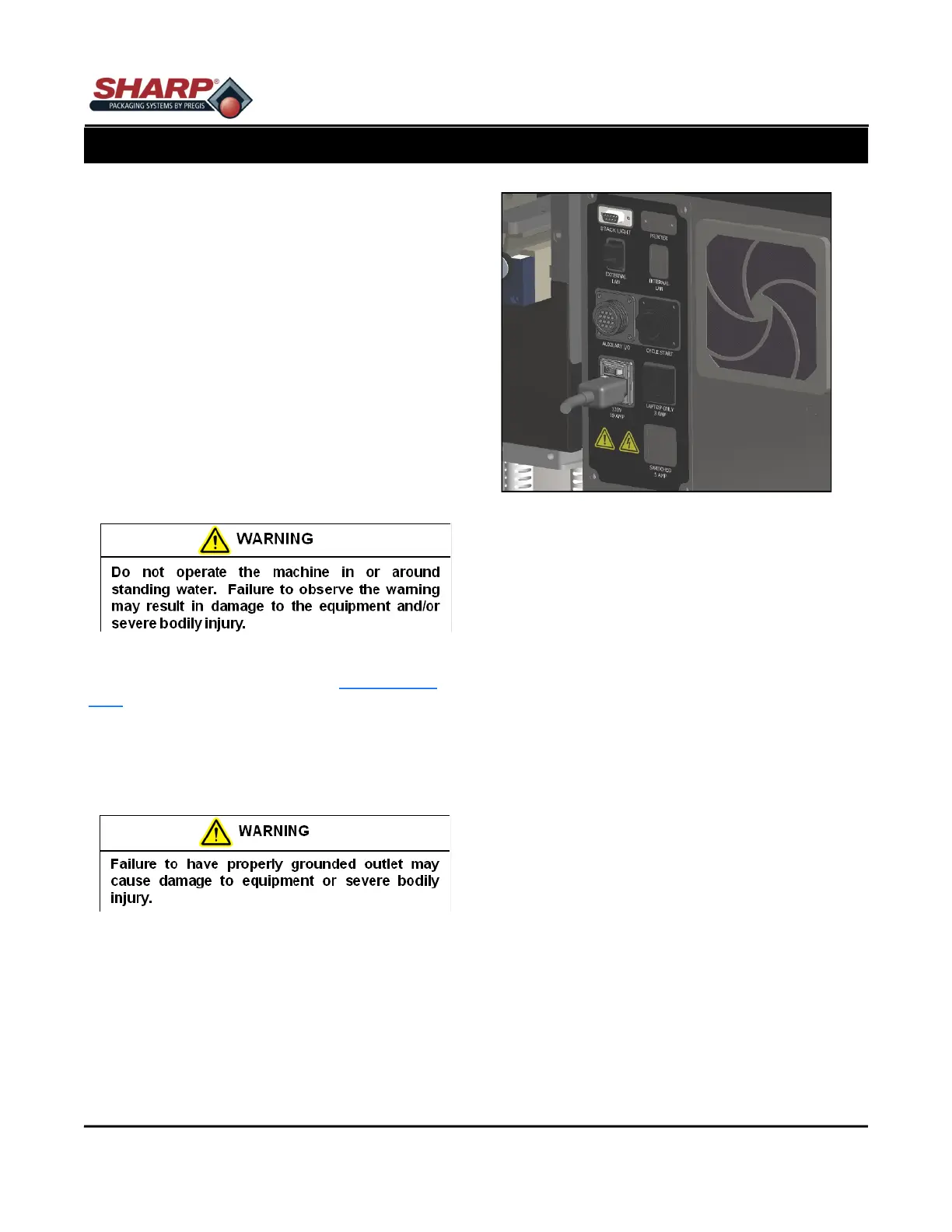
4. Place the female end of the electrical cord provid-
ed into the back of the machine, figure 2-1A.
5. Turn the switch to ON position.
Note: Power is only supplied to PLC, HMI/PC, and
Sensors. HMI/PC will boot automatically.
6. Release the E-Stop Button and press the Green
Power Button.
7. The machine now has full power.
* CE Models, see page 8-2
SECTION 2 - SETUP & ADJUST-
MACHINE PLACEMENT*
2-1
Figure 2-1A. Electrical Connections.*