5-16
VIBXPERT II 05.2012
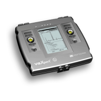
Orbit
The movement of the shaft axis* at constant speed is measured with
two non-contact sensors that are installed in an angular distance of
90°.
This enables identification of machine faults and damage to the shaft
that become apparent in the vibration behavior of the shaft and di-
rectly affect the path of the shaft (e.g. unbalance, misalignment, shaft
crack,rotationfault-formoredetails,seeVDI3839Sheets1and2).
When using 'filtered orbit', the signal is processed in an order filter
and therefore requires a keyphaser to provide a reference.
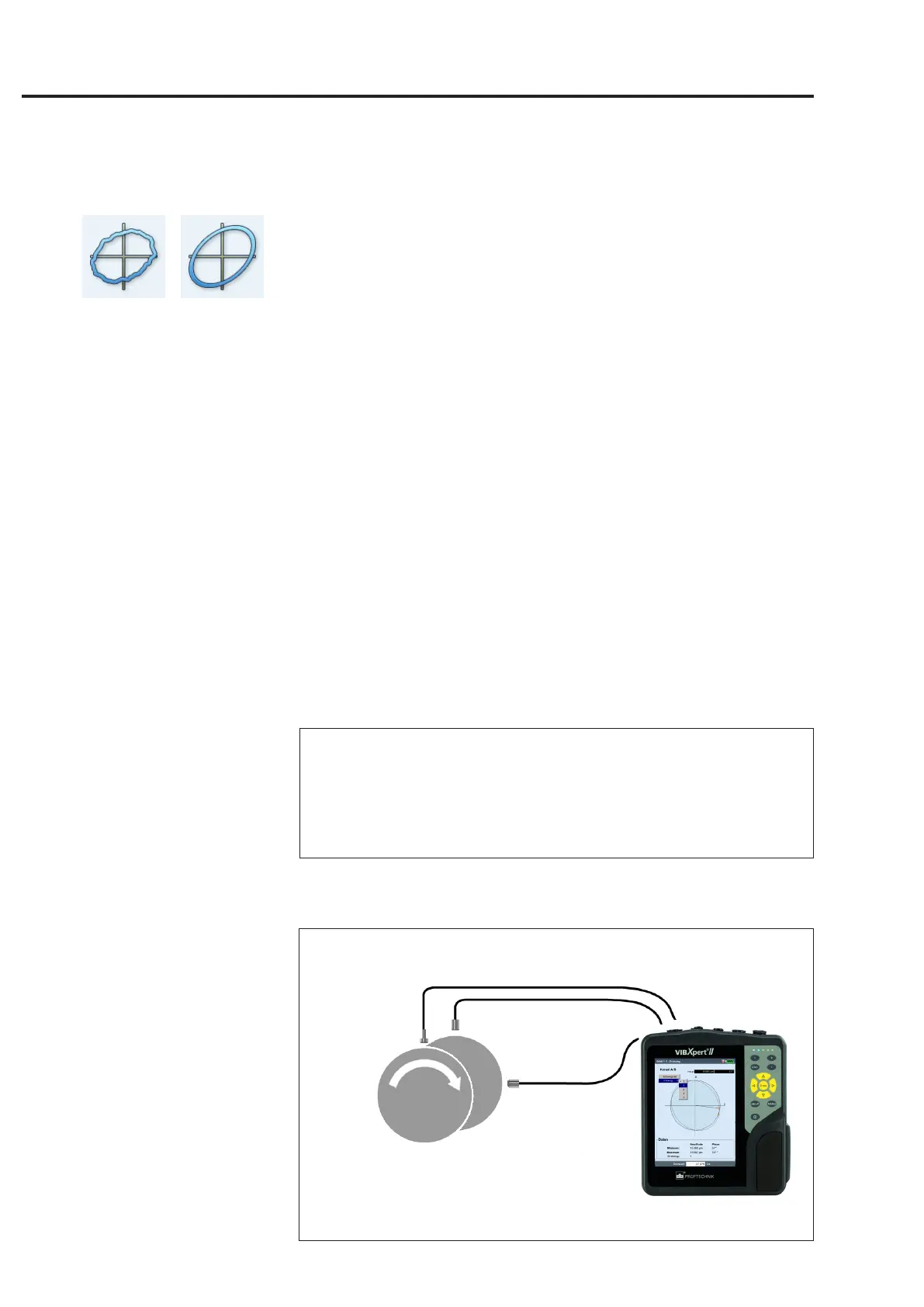
A typical measurement installation is shown in the following figure:
- The two displacement sensors are mounted in a single measure-
mentplaneatanangulardisplacementof90°onthemachine.
If this angular displacement is not possible, you can mount the
sensorsatanyangulardisplacementbetween5°and175°.Then
entertheangulardisplacementinthemeasurementsetup('Sen-
sorangle'parameter).However,measurementaccuracyislimited
when the sensor angle ≠90°.
- ThesensoronchannelAdenestheXdirectionandthe0°posi-
tion.
- Thekeyphaserismountedinthe0°position.
- Note the setting of the active edge for the trigger signal (see: Key-
phaserMenu/DeviceSetup,p.2-23).
The procedure for an orbit measurement is described in the follow-
ingstandards:ISO7919,ISO10817-1,VDI3839Sheet1.
A description of the measurement procedure with VIBXPERT can
befoundintheTechnicalInformationCM#18'Analysisofradial
shaft movement in journal bearings’ - available free on our website.
Typical installation
with inductive displacement sensors
Measurement tasks
Note
filtered
unfiltered
* The movement of the shaft axis while
the machine is running up / coasting
down is recorded with a shaft centerline
plot (see p. 5-12).
Channel A
(VIB 6.640)
Channel B
(VIB 6.640)
Keyphaser
(VIB 6.631)
 Loading...