11
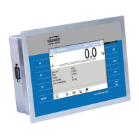
RS232 - DSUB15/F connector (female), front:
Pin8 - TxD2
Pin9 - 5VDC
Pin10 - GND
Pin13 - RxD2
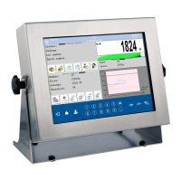
5.4. Inputs / Outputs
Standard PUE C32 indicator is equipped with 4 optoisolated inputs and 4
semiconductor outputs (solid-state relays). The signals are fed through
DSUB15/F connector.
I/O, RS232 DSUB15/F (female) connector, front:
Pin1 – GNDWE
Pin2 - OUT1
Pin3 - OUT2
Pin4 – COMM
Pin6 - IN4
Pin7 - IN3
Pin11 - IN2
Pin12 - IN1
Pin14 - OUT4
Pin15 - OUT3
5.4.1. Technical Specifications
Output parameters
Output quantity 4
Output type Solid-state relay
Cable cross-section 0.14 - 0.5mm
2
Maximum output current 0.5A DC
Maximum voltage 30VDC
Input parameters
Input quantity 4
Input type Optoisolated
Cable cross-section 0.14 – 0.5mm
2
Voltage range
5÷24VDC

 Loading...