Cableextension
Powercablescanbeextendedifrequired.The
followingrestrictionsapplytoanyextensiontothe
powercable:
•Cablemustbeofasuitablegaugeforthecircuit
load.
•Eachunitshouldhaveitsowndedicatedpower
cablewiredbacktothedistributionpanel.
Totallength
(max)Supplyvoltage
Cablegauge
(AWG)
12V18
0–5m(0–16.4ft)
24V20
12V14 5–10m
(16.4–32.8ft)
24V18
12V12 10–15m
(32.8–49.2ft)
24V16
12V12 15–20m
(49.2–65.5ft)
24V14
Note:a6xanda7xMFDsare12Vonlyproducts.NEVER
connecta12Vonlyproducttoa24Vsystem.
Sharingabreaker
Wheremorethan1pieceofequipmentsharesa
breakeryoumustprovideprotectionfortheindividual
circuits.E.g.byconnectinganin-linefuseforeach
powercircuit.
1
Positive(+)bar
2
Negative(-)bar
3
Circuitbreaker
4Fuse
Wherepossible,connectindividualitemsof
equipmenttoindividualcircuitbreakers.Wherethis
isnotpossible,useindividualin-linefusestoprovide
thenecessaryprotection.
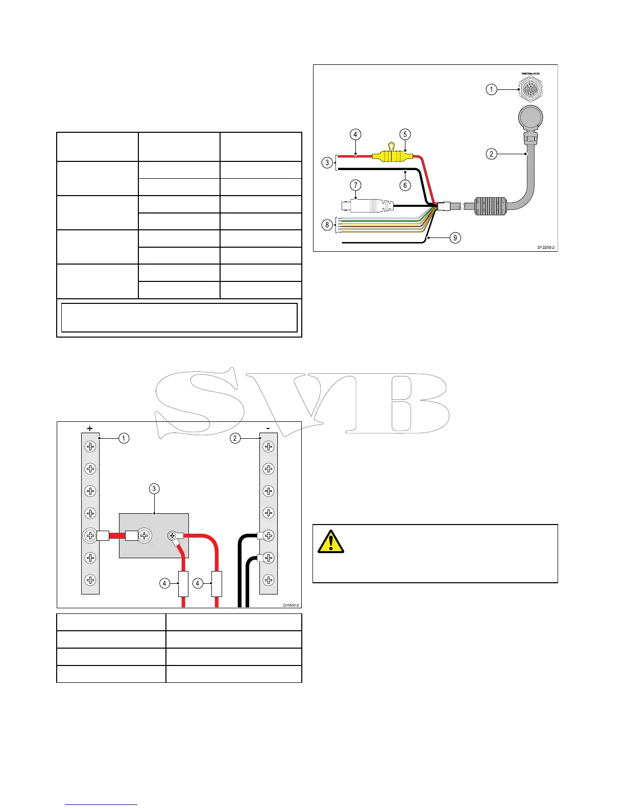
4.5Poweranddataconnection
ThedetailsbelowapplytoMFDswhichhavea
combinedpoweranddatacable.
1.Poweranddataconnection
2.Poweranddatacable
3.Connectiontovessel’s12V/24Vdcpower
supply
4.Redcable(positive)
5.Fuse
6.Blackcable(negative)
7.Videoinputcable
8.NMEA0183datacables
9.Shield(drain)wire(thinblackwire;mustbe
connectedtoRFgroundpoint)
Powerdistribution
Raymarinerecommendsthatallpowerconnections
aremadeviaadistributionpanel.
•Allequipmentmustbepoweredfromabreakeror
switch,withappropriatecircuitprotection.
•Allequipmentshouldbewiredtoindividual
breakersifpossible.
Warning:Productgrounding
Beforeapplyingpowertothisproduct,
ensureithasbeencorrectlygrounded,in
accordancewiththeinstructionsprovided.
Grounding—Dedicateddrainwire
Thepowercablesuppliedwiththisproductincludes
adedicatedshield(drain)wireforconnectiontoa
vessel'sRFgroundpoint.
ItisimportantthataneffectiveRFgroundis
connectedtothesystem.Asinglegroundpoint
shouldbeusedforallequipment.Theunitcanbe
groundedbyconnectingtheshield(drain)wireof
thepowercabletothevessel'sRFgroundpoint.
OnvesselswithoutanRFgroundsystemtheshield
(drain)wireshouldbeconnecteddirectlytothe
negativebatteryterminal.
Thedcpowersystemshouldbeeither:
•Negativegrounded,withthenegativebattery
terminalconnectedtothevessel'sground.
54aSeries/cSeries/eSeries

 Loading...