A-D Converter
M30240 Group
Rev.1.00 Sep 24, 2003 Page 104 of 360
1.2.24.2 Repeat mode
In repeat mode, the pin selected using the analog input pin select bit is used for repeated A-D conver-
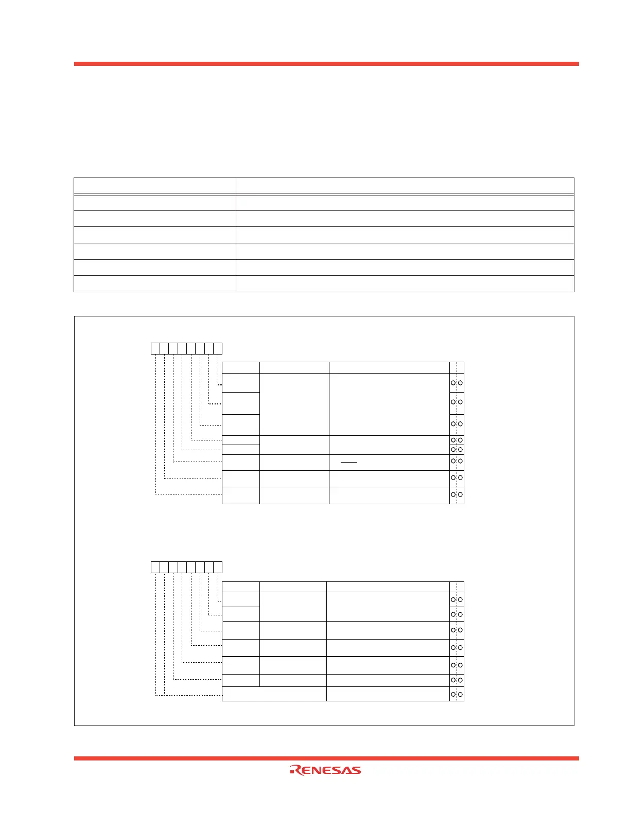
sion.Table 1.32 shows the specifications of repeat mode. Figure 1.100 shows the A-D control register
in repeat mode.
Figure 1.100: A-D conversion register in repeat mode
Table 1.32: Repeat mode specification
Item Specification
Function The pin selected by the analog input pin select bit is used for repeated A-D
Star condition Writing “1” to A-D conversion start flag
Stop condition Writing “0” to A-D conversion start flag
Interrupt request generation timing None generated
Input pin One of AN0 to AN7, as selected
Reading of result of A-D converter Read A-D register corresponding to selected pin
A-D control register 0 (Note 1)
Symbol
Address
When reset
ADCON0
03D6
16
00000XXX
2
b7 b6 b5 b4 b3 b2 b1 b0
Analog input pin
select bit
CH0
Bit symbol Bit name Function
CH1
CH2
A-D operation mode
select bit 0
MD0
MD1
Trigger select bit
0 : Software trigger
1 : AD
TRG trigger
TRG
ADST
A-D conversion start flag 0 : A-D conversion disabled
1 : A-D conversion started
Frequency select bit 0
0 : f
AD/4 is selected
1 : f
AD/2 is selected
CKS0
WR
A-D control register 1 (Note)
Symbol
Address
When reset
ADCON1
03D7
16
00
16
Bit name FunctionBit symbol
b7 b6 b5 b4 b3 b2 b1 b0
A-D sweep pin
select bit
SCAN0
SCAN1
MD2
BITS
8/10-bit mode select bit
0 : 8-bit mode
1 : 10-bit mode
VCUT
Vref connect bit
A-D operation mode
select bit 1
1 : Vref connected
WR
01
Invalid in repeat mode
0
0 0 0 : AN0 is selected
0 0 1 : AN
1 is selected
0 1 0 : AN
2 is selected
0 1 1 : AN
3 is selected
1 0 0 : AN
4 is selected
1 0 1 : AN
5 is selected
1 1 0 : AN
6 is selected
1 1 1 : AN
7 is selected (Note 2)
b2 b1 b0
0 1 : Repeat mode (Note 2)
b4 b3
1
Note 1: If the A-D control register is rewritten during A-D conversion, the conversion
result is indeterminate.
Note 2: When changing A-D operation mode, set analog input pin again.
Frequency select bit 1
0 : f
AD/2 or fAD/4 is selected
1 : f
AD is selected
CKS1
0 : Any mode other than repeat sweep mode 1
Note: If the A-D control register is rewritten during A-D conversion, the conversion
result is indeterminate.
Reserved bit Always set to "0"
0
0
 Loading...


