Timer A
M30240 Group
Rev.1.00 Sep 24, 2003 Page 66 of 360
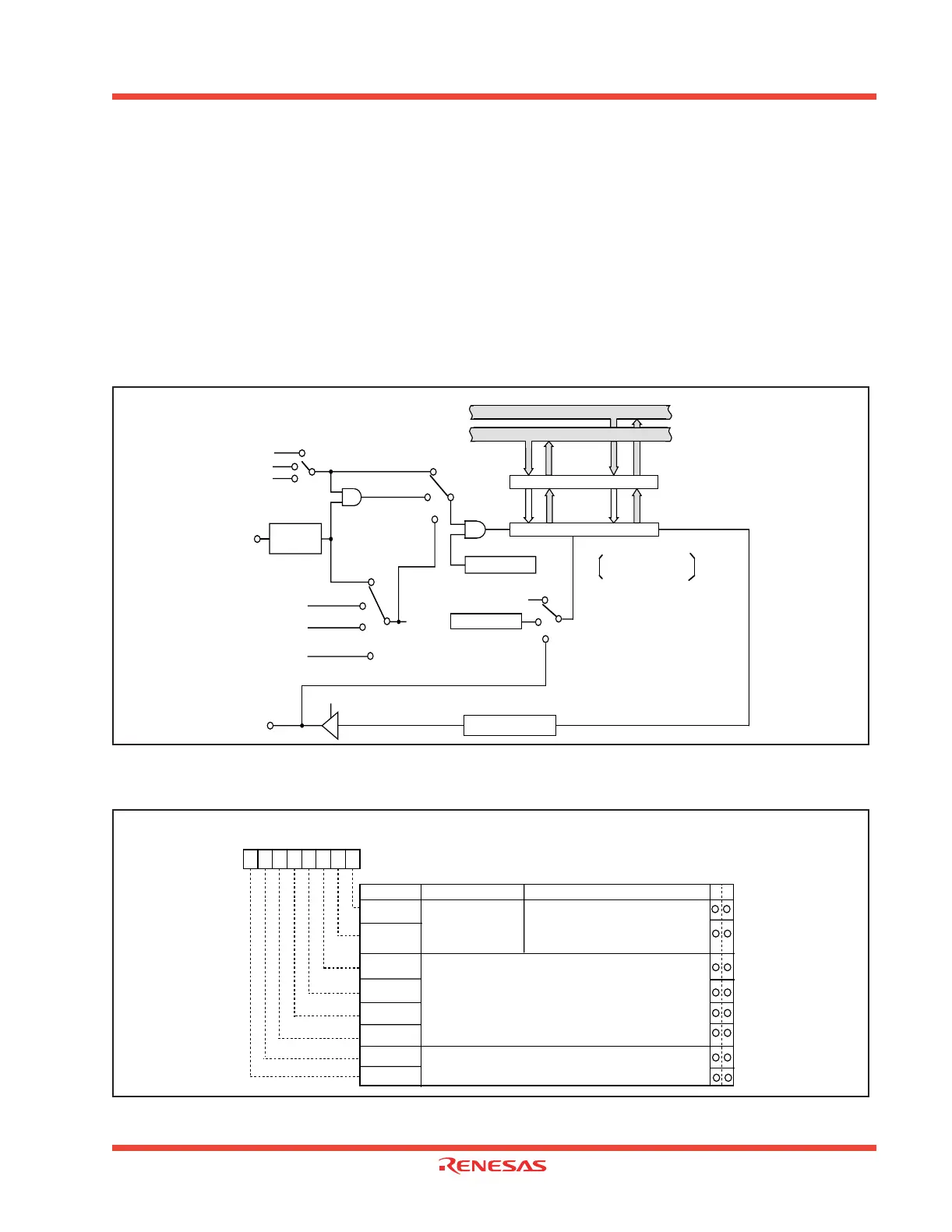
1.2.21 Timer A
Figure 1.59, Figure 1.60,Figure 1.61, and Figure 1.62 show the timer A-related registers.
Except in event counter mode, timers A0 through A4 all have the same function. Use the timer Ai mode
register (i = 0 to 4) bits 0 and 1 to choose the desired mode.
Timer A has the four operation modes listed as follows:
• Timer mode: The timer counts an internal count source.
• Event counter mode: The timer counts pulses from an external source or a timer over flow.
• One-shot timer mode: The timer stops counting when the count reaches “0000
16
”.
• Pulse width modulation (PWM) mode: The timer outputs pulses of a given width.
Figure 1.59: Block diagram of Timer A
Figure 1.60: Timer A related Registers (1)
Count start flag
(Address 0380
16
)
Up count/down count
TA i
Addresses TAj TAk
Timer A0 0387
16
0386
16
Timer A4 Timer A1
Timer A1 0389
16
0388
16
Timer A0 Timer A2
Timer A2 038B
16
038A
16
Timer A1 Timer A3
Timer A3 038D
16
038C
16
Timer A2 Timer A4
Timer A4 038F
16
038E
16
Timer A3 Timer A0
Always down count except
in event counter mode
Reload register (16)
Counter (16)
Low-order
8 bits
High-order
8 bits
Clock source
selection
• Timer
(gate function)
• Timer
• One shot
• PWM
f
1
f
8
f
32
External
trigger
TA i
IN
(i = 0 to 4)
TB2 overflow
• Event counter
Clock selection
TAj overflow
(j = i – 1. Note that j = 4 when i = 0)
Pulse output
Toggle flip-flop
TA i
OUT
(i = 0 to 4)
Data bus low-order bits
Data bus high-order bits
Up/down flag
Down count
(Address 0384
16
)
TAk overflow
Polarity
selection
(k = i + 1. Note that k = 0 when i = 4)
Timer Ai mode register
Symbol Address
When reset
TAiMR(i=0 to 4) 0396
16
to 039A
16
00
16
Bit name FunctionBit symbol WR
b7 b6 b5 b4 b3 b2 b1 b0
Operation mode
select bit
0 0 : Timer mode
0 1 : Event counter mode
1 0 : One-shot timer mode
1 1 : Pulse width modulation (PWM) mode
b1 b0
TMOD1
TMOD0
MR0
MR2
MR1
MR3
TCK1
TCK0
Count source select bit
Function varies with each operation mode
Function varies with each operation mode
 Loading...


