Clock-Asynchronous Serial I/O
M30240 Group
Rev.1.00 Sep 24, 2003 Page 200 of 360
2.5 Clock-Asynchronous Serial I/O (UART)
2.5.1 Overview
UART handles communications by means of character-by-character synchronization. The transmission
side and the reception side are independent of each other, so full-duplex communication is possible. The
following is an overview of the clock-asynchronous serial I/O.
2.5.1.1 Transmission/reception format
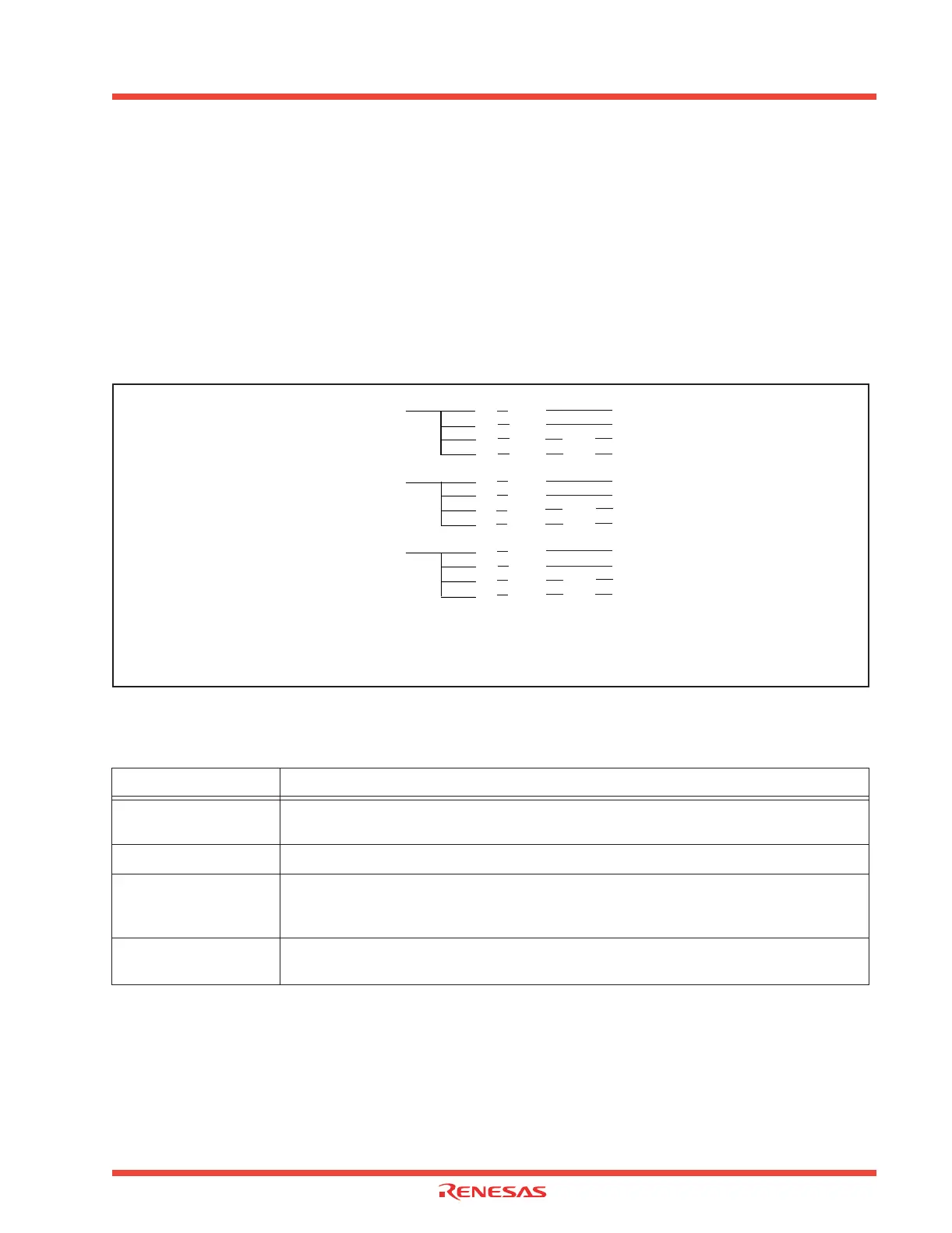
Figure 2.55 shows the transmission/reception format, and Table 2.16 shows the names and functions
of transmission data.
Figure 2.55: Transmission/reception format
Table 2.17: Transmission data names and functions
Name Function
ST (start bit)
A 1-bit “L” signal is added immediately before the character bits. This bit signals the start of
data transmission.
DATA (character bits) Transmission data set in the UARTi transmit buffer register.
PAR (parity bit)
A signal is added immediately after the character bits in order to increase data reliability. The
level of this signal varies so, the total number of 1’s in the character bits and this bit always
become even or odd depending on which parity is chosen.
SP (stop bit)
Either 1-bit or 2-bit “H” signal is added immediately after the character bits (after the parity bit
and when the parity bit is checked). This indicates the end of data transmission.
Transfer data length: 7 bits
1ST 7DATA 1SP
1ST 7DATA 2SP
1ST 7DATA 1PAR 1SP
1ST 7DATA 1PAR 2SP
Transfer data length: 8 bits
1ST 8DATA 1SP
1ST 8DATA 2SP
1ST 8DATA 1PAR 1SP
1ST 8DATA 1PAR 2SP
Transfer data length: 9 bits
1ST 9DATA 1SP
1ST 9DATA 2SP
1ST 9DATA 1PAR 1SP
1ST 9DATA 1PAR 2SP
ST : Start bit
DATA : Character bit (Transfer data)
PAR : Parity bit
SP : Stop bit
 Loading...


