Clock-Asynchronous Serial I/O
M30240 Group
Rev.1.00 Sep 24, 2003 Page 201 of 360
2.5.1.2 Transfer rate
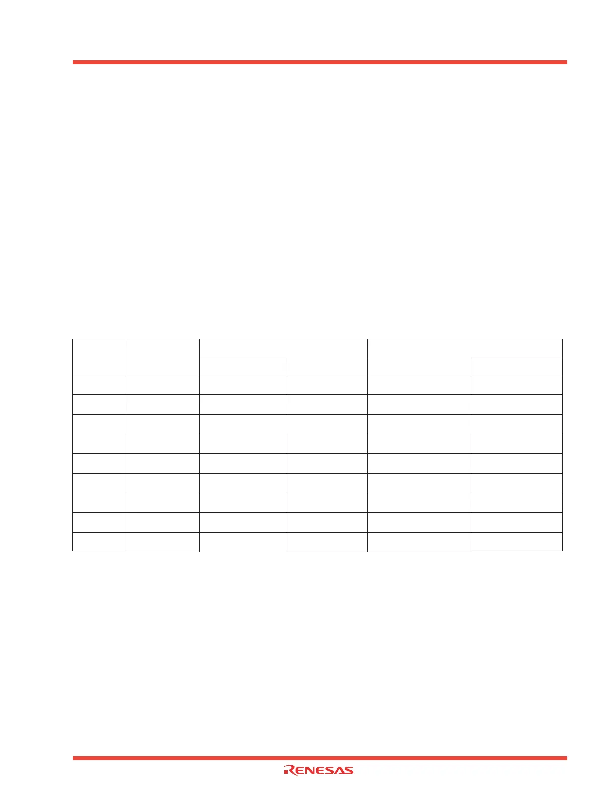
The divide-by-16 frequency, resulting from division in the bit rate generator (BRG), becomes the transfer
rate. The count source for the transfer rate register can be selected from f1, f8, f32, and the input from
the CLK pin. Clocks f1, f8, f32 are derived by dividing the CPU’s main clock by 1, 8, and 32 respectively.
Examples of baud rate settings are shown in Table 2.17 .
Transfer rate formulas
Table 2.18: Example of baud rate setting
When using internal clock: fi /16 (n+1)
fi = f
1
, f
8
, f
32
n = value in UARTi bit rate generator
When using external clock:
f
EXT
/16 (n+1)
f
EXT
= input on CLKi pin
n = value in UARTi bit rate generator
Baud rate
(bps)
BRGs
count source
System clock: 12 MHz System clock: 7.3728 MHz
BRGs set value:n Actual time (bps) BRGs set value:n Actual time (bps)
600 f8
155 (9B
16
)
601
95 (5F
16
)
600
1200 f8
77 (4D
16
)
1202
47 (2F
16
)
1200
2400 f8
38 (26
16
)
2404
23 (17
16
)
2400
4800 f1
155 (9B
16
)
4807
95 (5F
16
)
4800
9600 f1
77 (4D
16
)
9615
47 (2F
16
)
9600
14400 f1
51 (33
16
)
14423
31 (1F
16
)
14400
19200 f1
38 (26
16
)
19230
23 (17
16
)
19200
28800 f1
25 (19
16
)
28846
15 (F
16
)
28800
31250 f1
23 (17
16
)
31250 __ __
 Loading...


