UART0 to UART2
M30240 Group
Rev.1.00 Sep 24, 2003 Page 85 of 360
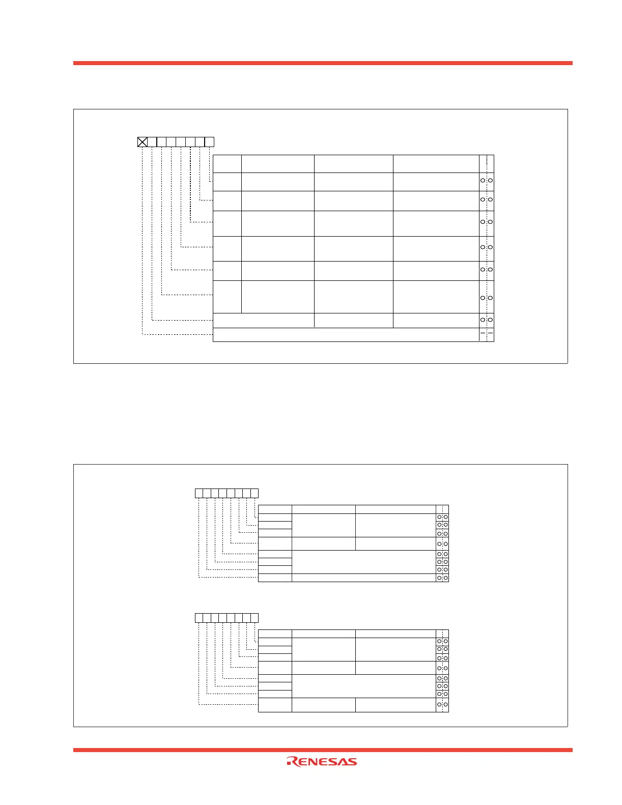
Figure 1.80: Serial I/O-related registers (5)
1.2.23.1 Clock synchronous serial I/O mode
The clock synchronous serial I/O mode uses a transfer clock to transmit and receive data. Figure 1.81
shows the UARTi transmit/receive mode register. Table 1.25 lists the specifications of the clock syn-
chronous serial I/O mode.
Figure 1.81: UARTi transmit/receive mode register in clock synchronous serial I/O mode
Note: When using multiple pins to output the transfer clock, the following requirements must be met:
• UART1 internal/external clock select bit (bit 3 at address 03A8
16
) = “0”.
UART transmit/receive control register 2
Symbol Address When reset
UCON 03B0
16
X0000000
2
b7 b6 b5 b4 b3 b2 b1 b0
Bit name
Bit
symbol
WR
Function
(During UART mode)
Function
(During clock synchronous
serial I/O mode)
CLKMD0
CLKMD1
UART0 transmit
interrupt cause select bit
UART0 continuous
receive mode enable bit
0 : Continuous receive
mode disabled
1 : Continuous receive
mode enable
UART1 continuous
receive mode enable bit
CLK/CLKS select bit 0
UART1 transmit
interrupt cause select bit
0 : Transmit buffer empty (Tl = 1)
1 : Transmission completed
(TXEPT = 1)
0 : Transmit buffer empty (Tl = 1)
1 : Transmission completed
(TXEPT = 1)
0 : Normal mode
(CLK output is CLK1 only)
1 : Transfer clock output
from multiple pins
function selected
0 : Continuous receive
mode disabled
1 : Continuous receive
mode enabled
Nothing is assigned.
This bit can neither be set nor reset. When read, its content is indeterminate.
0 : Transmit buffer empty (Tl = 1)
1 : Transmission completed
(TXEPT = 1)
0 : Transmit buffer empty (Tl = 1)
1 : Transmission completed
(TXEPT = 1)
Must always be “0”
U0IRS
U1IRS
U0RRM
U1RRM
Invalid
Invalid
Invalid
CLK/CLKS select
bit 1 (Note)
Valid when bit 5 = “1”
0 : Clock output to CLK1
1 : Clock output to CLKS1
Must always be “0”
Reserved
Must always be “0”
0
Symbol Address
When reset
UiMR(i=0,1) 03A0
16
, 03A8
16
00
16
CKDIR
UARTi transmit/receive mode registers
Internal/external clock
select bit
STPS
PRY
PRYE
SLEP
0 : Internal clock
1 : External clock
Bit name FunctionBit symbol WR
b7 b6 b5 b4 b3 b2 b1 b0
0 (Must always be “0” in clock synchronous serial I/O mode)
010
SMD0
SMD1
SMD2
Serial I/O mode select bit
0 0 1 : Clock synchronous serial
I/O mode
b2 b1 b0
0
Invalid in clock synchronous serial I/O mode
Symbol
Address
When reset
U2MR
0378
16
00
16
CKDIR
UART2 transmit/receive mode register
Internal/external clock
select bit
STPS
PRY
PRYE
IOPOL
0 : Internal clock
1 : External clock
Bit name FunctionBit symbol WR
b7 b6 b5 b4 b3 b2 b1 b0
010
SMD0
SMD1
SMD2
Serial I/O mode select bit
0 0 1 : Clock synchronous serial
I/O mode
b2 b1 b0
0
Invalid in clock synchronous serial I/O mode
TxD, RxD I/O polarity
reverse bit (Note)
0 : No reverse
1 : Reverse
Note 1: Usually set to "0".
 Loading...


