Timer A
M30240 Group
Rev.1.00 Sep 24, 2003 Page 155 of 360
2.2.2.5 Event Counter Mode with Free-run Type Selected
In event counter mode, select functions from those listed in Table 2.5 . An example using the indicated
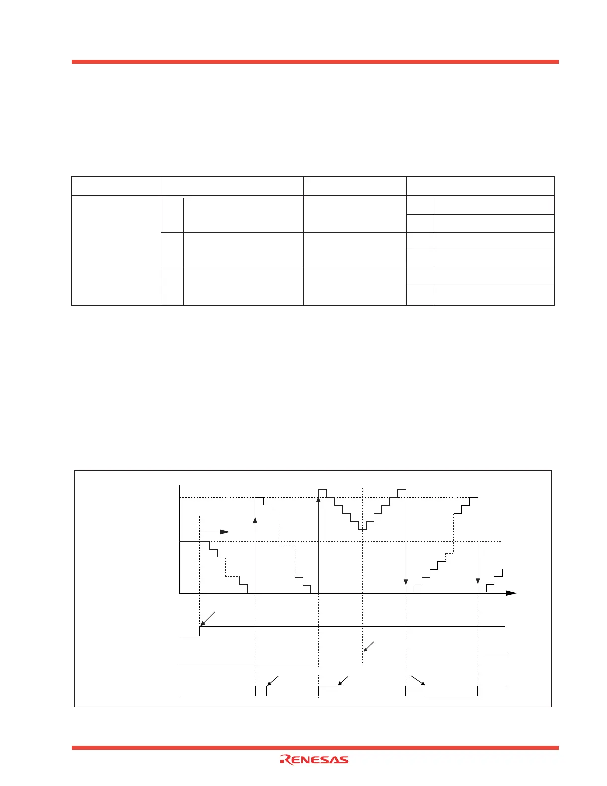
options is described below. Figure 2.15 shows the operation timing, and Figure 2.16 shows the set-up
procedure.
Table 2.5: Timer A event counter mode and free-run type functions
Note j = i - 1, but j = 4 when i = 0
Operation
(1) Setting the count start flag to “1” causes the counter to count the falling edges of the count source.
(2) Even if an underflow occurs, the content of the reload register is not reloaded, but the count con-
tinues. At this time, the Timer Ai interrupt request bit goes to “1”.
(3) If switching from an up count to a down count or vice versa while a count is in progress, the switch
takes effect from the next effective edge of the count source.
(4) Even if an overflow occurs, the content of the reload register is not reloaded, but the count contin-
ues. At this time, the Timer Ai interrupt request bit goes to “1”.
Figure 2.15: Event counter mode timing and free-run type operation
Item
Set-up Item Set-up
Count source
O
Input signal to TAi
IN
(counting
falling edges)
Pulse output function
O No pulses output
Pulses output
Input signal to TAi
IN
(counting
rising edges)
Count operation type
Reload type
O Free-run type
Timer overflow (TB2/TAj
overflow)
Factor for switching
between up and down
O Up/Down flag contents
Input signal to TAi
OUT
FFFF16
n
0000
16
Time
Counter content (hex)
n = reload register content
(1) Start count
Count start flag
“1”
“0”
Timer Ai interrupt
request bit
“1”
Cleared to “0” when interrupt request is accepted, or cleared by software
“0”
Up/down flag
“1”
“0”
Set to “1” by software
(2) Underflow
(3) Switch count
(4) Overflow
Set to “1”
by software
 Loading...


