Power Control
M30240 Group
Rev.1.00 Sep 24, 2003 Page 277 of 360
sequence.
When an interrupt is generated in stop mode, CM10 becomes “0” and stop mode is cleared.
Starting oscillation and supplying Internal clock Φ executes the interrupt sequence as follows:
In the interrupt sequence, the processor carries out the following in the sequence given:
(a) The CPU gets the interrupt information (the interrupt number and interrupt request level) by reading
address 00000
16
. The interrupt request bit of the interrupt written in address 00000
16
will then be set
to “0”.
(b) Saves the content of the flag register (FLG) as it was immediately before the start of the interrupt
sequence in the temporary register (Note) within the CPU.
(c) Sets the interrupt enable flag (I flag), the debug flag (D flag), and the stack pointer assignment flag
(U flag) to “0” (the U flag, however does not change if the INT instruction, in software interrupt numbers
32 through 63, is executed)
(d) Saves the content of the temporary register (Note) within the CPU in the stack area.
(e) Saves the content of the program counter (PC) in the stack area.
(f) Sets the interrupt priority level of the accepted instruction in the IPL.
(g) After the interrupt sequence is completed, the processor resumes executing instructions from the
first address of the interrupt routine.
Note: This register cannot be utilized by the user.
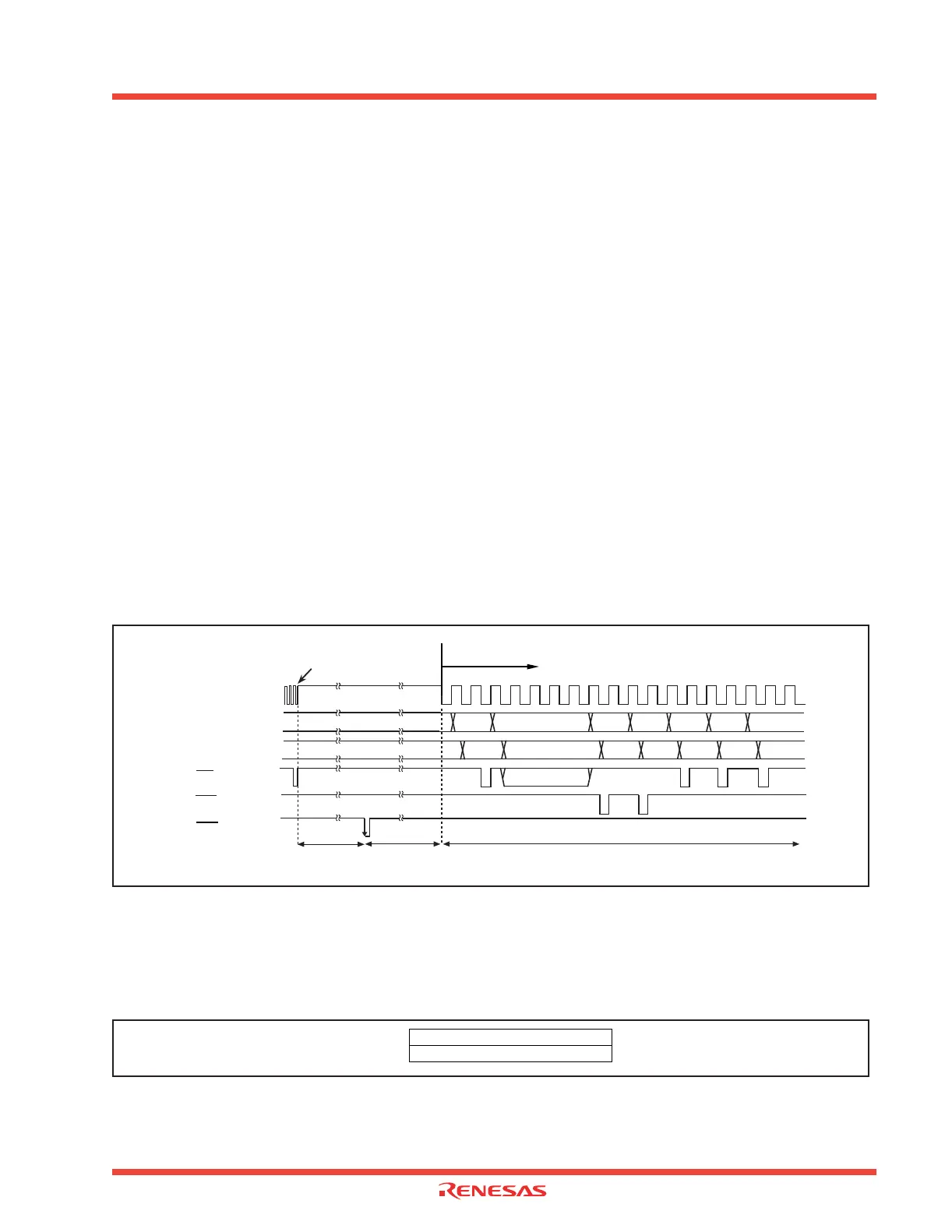
Figure 2.125 shows the sequence of returning from stop mode.
Figure 2.125: Sequence of returning from stop mode
2.12.1.6 Related registers
Figure 2.126 shows the memory map of power control-related registers, and Figure 2.127 shows power
control-related registers.
Figure 2.126: Memory map of power control related registers
Address
00000
Interrupt
information
Internal clock Φ
Address bus
Data bus
Indeterminate SP-2 SP-4 vec vec+2
Indeterminate
SP-2
contents
SP-4
contents
vec
contents
vec+2
contents
PC
Writing “1” to CM10
(all clock stop control bit)
Oscillation start-upStop mode
Interrupt sequence approximately 20 cycle (13.3µ s)
(Single-chip mode, f(X
IN) = 12MHz)
RD
WR
Indeterminate
Operated by divided-by-8 mode
INTi
000616
000716
System clock control register 0 (CM0)
System clock control register 1 (CM1)
 Loading...


