Address Match Interrupt
M30240 Group
Rev.1.00 Sep 24, 2003 Page 270 of 360
2.10.2 Operation
This section describes an example of the address match interrupt operation. Figure 2.117 shows the
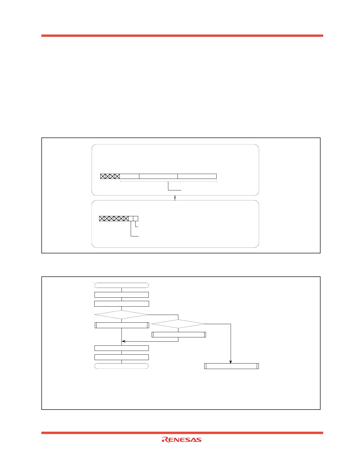
set-up procedure of the address match interrupt, and Figure 2.118 shows an overview of the address
match interrupt handling routine.
(1) The address match interrupt handling routine sets an address to be used to cause the address match
interrupt register to generate an interrupt.
(2) Setting the address match enable flag to “1” enables an interrupt to occur.
(3) An address match interrupt occurs immediately before the instruction in the address indicated by the
address match interrupt register while a program is executed.
Figure 2.117: Set-up procedure of address match interrupt
Figure 2.118: Overview of address match interrupt handling routine
Can be set to “00000 16” to “FFFFF 16”
b7 b0
(b23) (b16)
b7 b0
Address match interrupt register 0 [Address 0012 16 to 001016]
RMAD0
Address match interrupt register 1 [Address 0016
16 to 001416]
RMAD1
Setting the address match interrupt enable register
Address match interrupt enable register [Address 0009 16]
AIER
Address match interrupt 0 enable bit
1: Interrupt enabled
b7 b0
b7 b0
(b15) (b8)
b4
(b20)
b3
(b19)
Address match interrupt 1 enable bit
1: Interrupt enabled
Setting the address match interrupt register
Address match interrupt routine
[1] Storing registers
[2] Determine the interrupt address
Address match 0?
Address match 0 program
[3] Rewriting the stack
Restoring registers
REIT
No
Ye s
Address match 1?
Address match 1 program
No
Ye s
Handling an error
[1]
Storing the contents of the registers holding the main program status to be kept.
[2] Determining the interrupt address
Determining which factor generated the interrupt.
[3] Rewriting the stack
Rewriting the return address.
Explanation:
 Loading...


