Universal Serial Bus
M30240 Group
Rev.1.00 Sep 24, 2003 Page 302 of 360
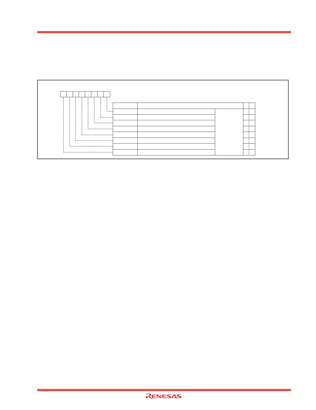
3.2.2.10 USB Endpoint Enable Register
The USB Endpoint Enable Register, shown in Figure 3.16, is used to enable/disable an individual endpoint. End-
point 0 is always enabled and cannot be disabled by firmware. All endpoints are enabled after reset.
Figure 3.16: USB Endpoint Enable Register (USBEPEN)
3.2.2.11 USB Endpoint 0 Control and Status Register
The endpoint 0 CSR (Control and Status Register) contains the control and status information for end-
point 0. The following bits make up Endpoint 0 CSR.
• OUT_PKT_RDY Flag
This flag becomes “1” when a valid SETUP/OUT token is received from the host CPU. After reading
the OUT FIFO, the OUT_PKT_RDY bit should be set to “0” by writing “1” to the
SERVICED_OUT_PKY_RDY flag (the OUT_PKY_RDY flag should not be set to “0” until the decoding
of the request from the host CPU has been completed).
• IN_PKT_RDY Bit
This bit should be “1” when a data packet has been written to the endpoint 0 IN FIFO, The USB func-
tion control unit clears this bit to “0” when the IN FIFO data has been successfully transmitted to the
host or when the SETUP_END flag becomes “1”.
• SEND_STALL Bit
This should be set to “1” when an invalid standard request is received from the host CPU. By doing
this the USB function control unit will transmit a stall handshake signal in response to all of the IN/OUT
transactions. When the OUT_PKT_RDY flag is “1” the SERVICED_OUT_PKT_RDY bit should be at
“1” simultaneously with the SEND_STALL bit being at ì0î to thereby get the OUT_PKT_RDY flag
cleared to “0”.
• DATA_END Bit
This bit should be set to “1” when the last data packet is written to the FIFO (IN data phase) or when
the last data packet is read from the FIFO (OUT data phase). This notifies the USB function control
unit that the processing of the total amount of data indicated during the set up phase has been com-
pleted. The USB function control unit automatically sets this bit to “0” after the status phase completes.
While this bit is set to “1”, any requests from the host CPU to transmit or receive data are ignored, and
the USB function control unit sends back a STALL handshake signal to the host CPU.
• FORCE_STALL Flag
This flag is set to “1” to report an error status if any of the following conditions occur:
• Receive IN token before a SETUP stage,
Bit Symbol
Bit Name Function
R W
EP1_OUT Endpoint 1 OUT FIFO enable bit
Symbol
USBEPEN
Address
030B
16
When reset
FF
16
USB Endpoint Enable Register
b7 b5b6 b4 b3 b2 b1 b0
O O
EP1_IN
EP2_OUT
EP2_IN
EP3_OUT
EP3_IN
EP4_OUT
EP4_IN
O O
O O
O O
O O
O O
O O
O O
Endpoint 1 IN FIFO enable bit
Endpoint 2 OUT FIFO enable bit
Endpoint 2 IN FIFO enable bit
Endpoint 3 OUT FIFO enable bit
Endpoint 2 IN FIFO enable bit
Endpoint 4 OUT FIFO enable bit
Endpoint 4 IN FIFO enable bit
0 : Disabled
1 : Enabled
 Loading...


