Frequency Synthesizer
M30240 Group
Rev.1.00 Sep 24, 2003 Page 131 of 360
1.5 Applications
1.5.1 Frequency Synthesizer
This section presents the recommended method of setting up and using the frequency synthesizer that
generates the 48MHz clock needed by the USB FCU and the DC-DC converter that provides power to
the D+/D- drivers.
1.5.1.1 Reset of USB-related registers
The special function registers (SFRs) that govern the operation of the frequency synthesizer, DC-DC
converter and USB FCU are affected by one or more reset events. The addresses of the special function
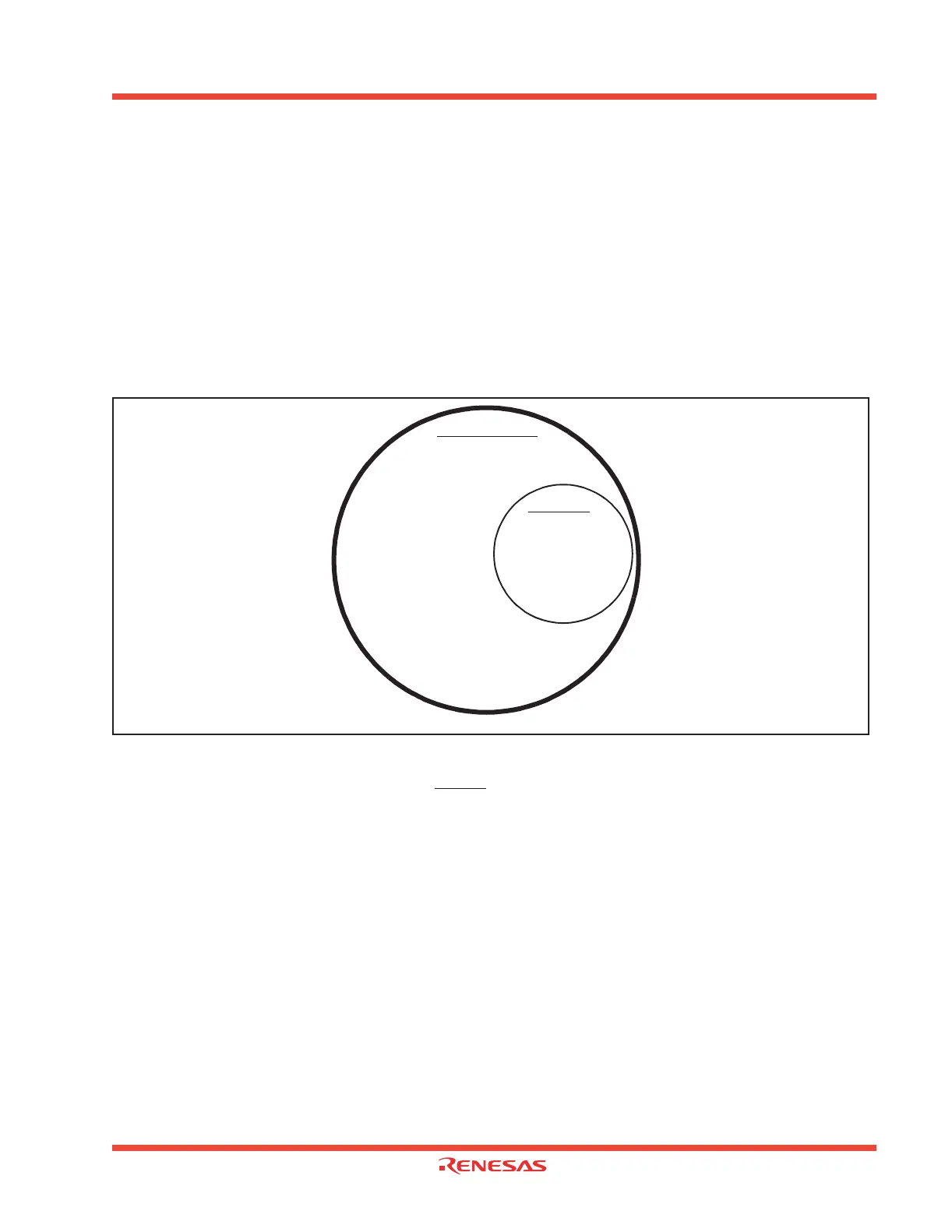
registers (SFRs) that are affected by Hardware Reset, USB Reset, or both are shown in Figure 1.116.
Figure 1.116: SFR Reset Venn Diagram
All resetable SFRs, including SFRs and other registers internal to the USB FCU, are affected by a
Hardware Reset, which occurs when the RESET
pin is brought low or an undefined opcode is fetched.
See Section 2.4 for a complete listing of SFRs and their reset values.
Only registers internal to the USB FCU are reset when a USB Reset sent by the Host/Hub is detected.
These USB registers are reset to their default values except for bit 5 of USBIS2 (USB Reset Interrupt
Status Flag), which is set to a “1”. USB FCU registers are registers from address 0300
16
to 033C
16
and
all other registers within the USB FCU, many of which the MCU does not have direct access to (e.g.
FIFO address pointers). The USB FIFO registers are empty after USB reset because the FIFO ad-
dress pointers are reset. However, the physical contents of the FIFOs are not set to all ‘1‘s or all ‘0‘s.
Other SFRs such as USBC, FSC, and CM0, CM1 are not affected by a USB Reset.
Hardware Reset
USB Reset
SFR Registers:
0004
16
to 005F
16
,
0378
16
to 03FF
16
000C (USBC),
03DC
16
(FSC)
SFR Registers:
0300
16
to 033C
16
(USB FCU registers)
 Loading...


