Clock-Asynchronous Serial I/O
M30240 Group
Rev.1.00 Sep 24, 2003 Page 218 of 360
2.5.2.3 Transmission compliant with SIM interface
For transmitting data in UART mode (compliant with SIM interface), select functions from those listed in
Table 2.22 . An example using the indicated options is described below. Figure 2.68 shows the operation
timing, and Figure 2.69 and Figure 2.70 show the set-up procedures.
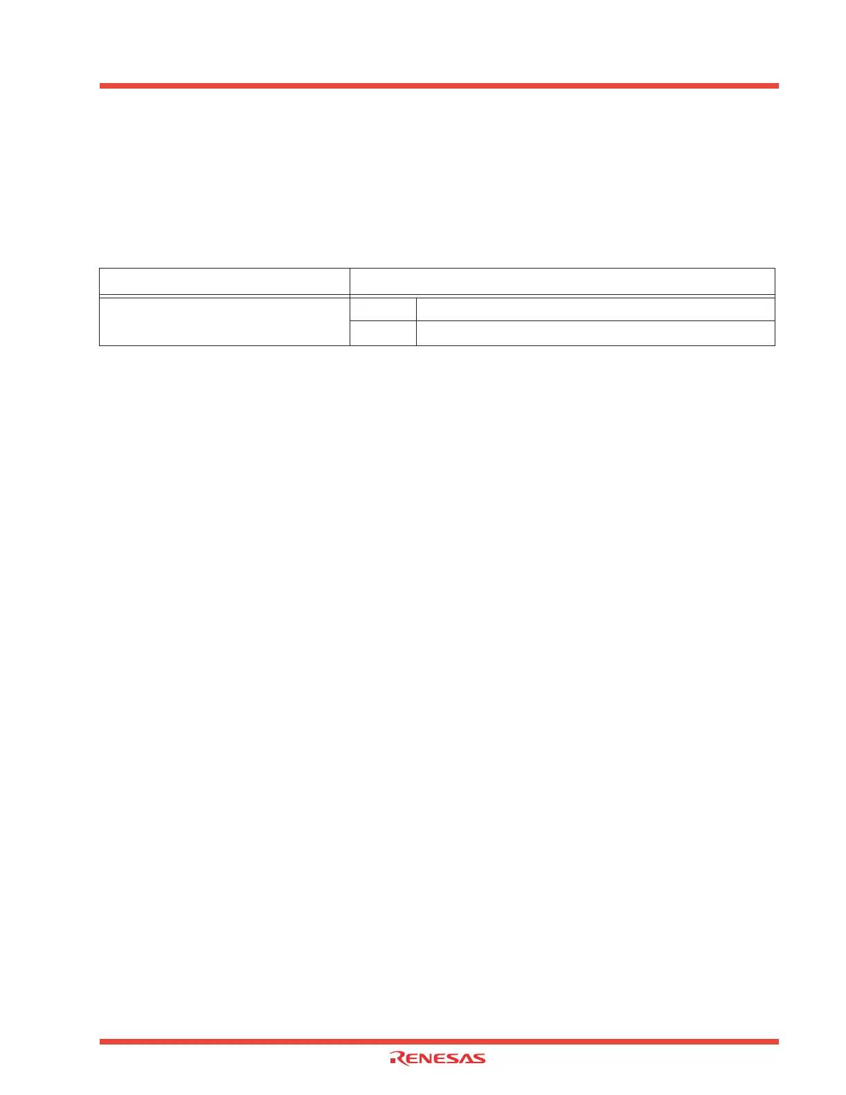
Table 2.22: Serial I/O transmission compliant with SIM interface functions
Operation
(1) Setting the transmit enable bit and receive enable bit to “1” and writing transmission data to the
UART2 transmit buffer register readies the data transmissible status. Set UART2 transfer interrupt to
enabled.
(2) Transmission data held in the UART2 transmit buffer register is transmitted to the UART2 transmit
register. At this time, the first bit (the start bit) of the transmission data is transmitted from the TxD2
pin. Then, data is transmitted, bit by bit, in sequence: LSB, ····, MSB, parity bit, and stop bit(s).
(3) When the stop bit(s) is (are) transmitted, the transmit register empty flag goes to “1”, which indi-
cates that transmission is completed. At this time, the UART2 transmit interrupt request bit goes to “1”.
The transfer clock stops at “H” level.
(4) If the transmission condition of the next data is ready when transmission is completed, a start bit
is generated following the stop bit(s), and the next data is transmitted.
(5) If a parity error occurs, an L is output from the SIM card, and the RxD2 terminal goes to the “L”
level. Check the RxD2 terminal's level within the UART2 transmission interrupt routine, and if it is
found to be at the “L” level, then handle the error.
Notes:
• The parity error level is determined within the UART2 transmission interrupt. When a transmission
interrupt request occurs, set the priority level of the transmission interrupt higher than those of other
interrupts so that the interrupt routine can be immediately carried out. Either in the main routine or
in an interrupt routine, the interrupt inhibition time has to be made as short as possible.
• Set the RxD2 terminal's direction register to input.
Item
Set-up
Transfer data format
O Direct format
Inverse format
 Loading...


