Clock-Asynchronous Serial I/O
M30240 Group
Rev.1.00 Sep 24, 2003 Page 221 of 360
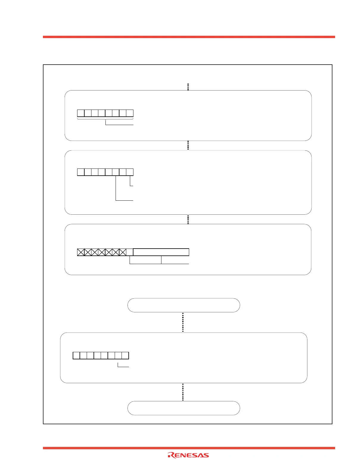
Figure 2.70: Set-up procedure of transmission in UART mode (compliant with SIM interface) (2)
Continued from the previous page
Setting UART2 bit rate generator
UART2 bit rate generator [Address 0379 16]
U2BRG
Can be set from
00
16 to FF16 (Note)
b7 b0
Note: Write to UARTi bit rate generator when transmission/reception is halted.
Reception enabled
UART2 transmit/receive control register 1 [Address 037D 16]
U2C1
b7 b0
Receive enable bit
1 : Reception enabled
11
Transmit enable bit
1 : Transmission enabled
Writing transmit data
UART2 transmit buffer register [Address 037B 16, 037A16]
U2TB
b7 b0 b7 b0
(b15) (b8)
Setting transmission data
UART2 transmit interrupt
Confirm RXD2 pin level
Port P7 register [Address 03ED 16]
P7
Port P7
1 register
0 : "L" level
1 : "H" level
b7 b0
REIT instruction
 Loading...


