UART0 to UART2
M30240 Group
Rev.1.00 Sep 24, 2003 Page 91 of 360
1.2.23.2 Clock asynchronous serial I/O (UART) mode
The UART mode allows transmitting and receiving data after setting the desired transfer rate and
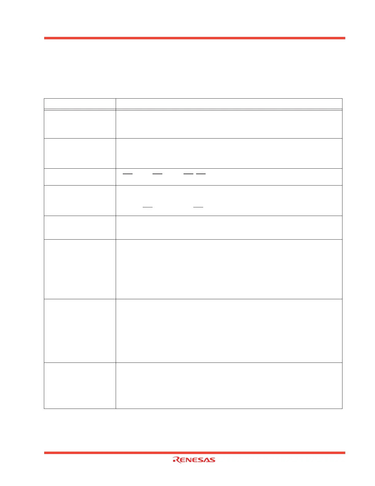
transfer data format. Table 1.27 lists the specifications of the UART mode.
Table 1.27: Specifications of UART mode
Note 1: ‘n’ denotes the value 00
16
to FF
16
that is set to the UARTi bit rate generator.
Note 2: fEXT is input from the CLKi pin. External clock cannot be selected in UART2.
Note 3: If an overrun error occurs, the UARTi receive buffer will have the next data written in. Note also that the UARTi receive interrupt
request bit is not set to “1”
Item Specification
Transfer data format
• Character bit (transfer data): 7 bits, 8 bits, or 9 bits as selected
• Start bit: 1 bit
• Parity bit: Odd, even, or nothing as selected
• Stop bit: 1 bit or 2 bits as selected
Transfer clock
• When internal clock is selected (bit 3 at addresses 03A0
16
, 03A8
16
, 0378
16
= “0”):
fi/16(n+1) (Note 1) fi = f1, f8, f32
• When external clock is selected (bit 3 at addresses 03A0
16
, 03A8
16
=“1”):
fEXT/16(n+1)(Note 1) (Note 2)
Transmission/reception
control
• CTS
function/RTS function/ CTS, RTS function disabled
Transmission start condition
• To start transmission, the following requirements must be met:
Transmit enable bit (bit 0 at addresses 03A5
16
, 03AD
16
, 037D
16
) = “1”
Transmit buffer empty flag (bit 1 at addresses 03A5
16
, 03AD
16
, 037D
16
) = “0”
When CTS
function selected, CTS input level = “L”
Reception start condition
• To start reception, the following requirements must be met:
Receive enable bit (bit 2 at addresses 03A5
16
, 03AD
16
, 037D
16
) = “1”
Start bit detection
Interrupt request generation
timing
• When transmitting
Transmit interrupt cause select bits (bits 0,1 at address 03B0
16
, bit4 at address 037D
16
) = “0”:
Interrupts requested when data transfer from UARTi transfer buffer register to UARTi transmit
register is completed
Transmit interrupt cause select bits (bits 0, 1 at address 03B0
16
, bit4 at address 037D
16
) = “1”:
Interrupts requested when data transmission from UARTi transfer register is completed
• When receiving
Interrupts requested when data transfer from UARTi receive register to UARTi receive buffer
register is completed
Error detection
• Overrun error (Note 3)
This error occurs when the next data is ready before contents of UARTi receive buffer register are
read out
• Framing error
This error occurs when the number of stop bits set is not detected
• Parity error
This error occurs when if parity is enabled, the number of 1’s in parity and character bits does not
match the number of 1’s set
• Error sum flag
This flag is set (= 1) when any of the overrun, framing, and parity errors is encountered
Select function
• Sleep mode selection (UART0, UART1)
This mode is used to transfer data to and from one of multiple slave micro-computers
•Serial data logic switch (UART2)
This function is reversing logic value of transferring data. Start bit, parity bit and stop bit are not
reversed.
•TxD, RxD I/O polarity switch (UART2)
This function is reversing TxD port output and RxD port input. All I/O data level is reversed.
 Loading...


