Interrupts
M30240 Group
Rev.1.00 Sep 24, 2003 Page 28 of 360
1.2.12 Interrupts
Table 1.9 and Table 1.10 show the interrupt sources and vector table addresses. When an interrupt is
received, the program is executed from the address shown by the respective interrupt vector.
The vector table addresses for the interrupts in Table 1.9 are fixed (interrupt vector addresses). These
interrupts are not affected by the interrupt enable flag (I flag) (non-maskable interrupts).
The vector table addresses for the interrupts in Table 1.10 are variable, being determined as relative to
the fixed address in the interrupt table register (INTB). These interrupts can be enabled or disabled using
the interrupt enable flag (I flag) (maskable interrupts). Sixty four vectors can be set in the interrupt table
register (INTB). Any of software interrupts 0 to 63 can be assigned to each vector. By using the INT
instruction to specify a software interrupt number, the program can be executed starting at the address
indicated by the respective vector. The BRK instruction interrupt has interrupt vectors in both the fixed
vector address and variable vector address. When the contents of FFFE4
16
through FFFE7
16
are all
“FF
16
”, the program is executed from the address shown in the BRK instruction interrupt vector in the
variable vector address.
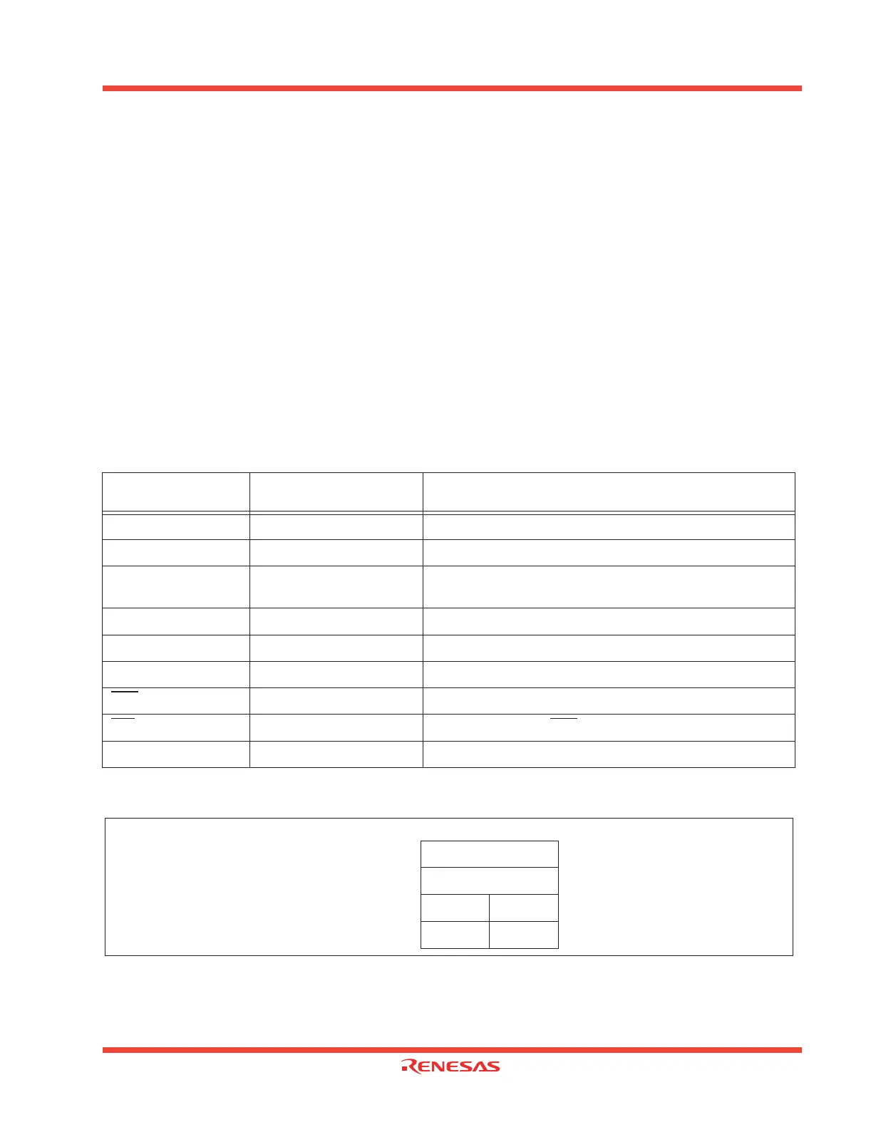
Specify the starting address of the interrupt program in the interrupt vector. Figure 1.15 shows the format
for specifying the address.
Table 1.9: Interrupt vectors with fixed addresses
Note: Interrupts used for debugging purposes only
Figure 1.15: Format for specifying interrupt vector addresses
Interrupt source
Vector table addresses
Address(L) to Address(H)
Remarks
Undefined instruction
FFFDC
16
to FFFDF
16
Interrupt on UND instruction
Overflow
FFFE0
16
to FFFE3
16
Interrupt on INTO instruction
BRK instruction
FFFE4
16
to FFFE7
16
If the vector is filled with FF
16
, program execution starts from
the address shown by the vector in the variable vector table
Address Match
FFFE8
16
to FFFEB
16
There is an address-matching interrupt enable bit
Single Step (Note)
FFFEC
16
to FFFEF
16
Do not use
Watchdog timer
FFFF0
16
to FFF3
16
DBC (Note)
FFFF4
16
to FFFF7
16
Do not use
NMI
FFFF8
16
to FFFFB
16
External interrupt by NMI pin
Reset
FFFFC
16
to FFFFF
16
Vector address + 0
Vector address + 1
Vector address + 2
Vector address + 3
Low address
Mid address
0 0 0 0
High
address
0 0 0 0 0 0 0 0
MSB LSB
 Loading...


