Universal Serial Bus
M30240 Group
Rev.1.00 Sep 24, 2003 Page 308 of 360
Figure 3.22: USB Endpoint x OUT CSR
3.2.2.17 USB Endpoint x OUT MaxP Register
This register indicates the Maximum Packet size (MaxP) of Endpoint x (x=1-4) OUT packet. The MaxP
register should be set when the SET_DESCRIPTOR command is received from the host CPU. When
MaxP > half of the FIFO size, single buffer mode is selected. When MaxP <= half the FIFO size, double
buffer mode is selected.
Figure 3.23 shows the structure of the USB Endpoint x OUT MaxP Register
Figure 3.23: USB Endpoint xOUT MaxP
3.2.2.18 USB Endpoint x OUT Write Count Register
This register contains the current number of bytes in the Endpoint x (x = 1-4) OUT FIFO. The USB
Function Control unit sets the value of this register after a data packet is completely received from the
host CPU. Refer to this register when the data is read from the OUT FIFO.
Figure 3.24 shows the structure of the USB Endpoint x(x = 1-4) OUT Write Count Register
Figure 3.24: USB Endpoint x OUT WRT CNT Register
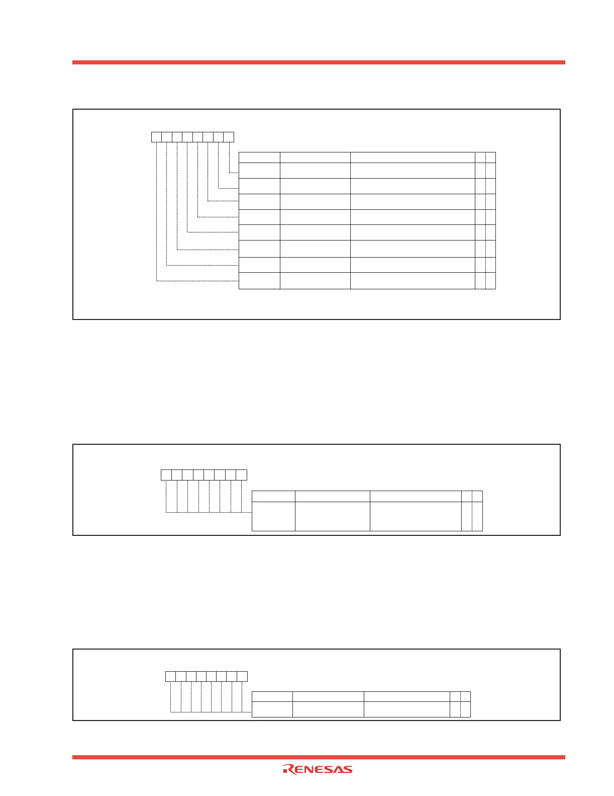
Bit Symbol Bit Name Function R W
OUTxCSR0
OUT_PKT_RDY Flag
0: Not ready
1: Ready
O O
Symbol
EPiOCS (i=1-4)
Address
031A
16
, 0322
16
, 032A
16
, 0332
16
When reset
00
16
USB Endpoint x OUT Control and Status Register (Note 3)
b7 b5b6 b4 b3 b2 b1 b0
OUTxCSR1
OVER_RUN Flag
0: No FIFO OVerrun
1: FIFO overrun occured
O O
OUTxCSR2 SEND_STALL Bit
0: No action
1: Stall OUT Endpoint x by CPU
O O
Note 1
Note 1
Note 1: Write "0" only or Read
Note 2: Write only or Read
Note 3: Refer to Programming Notes in Chapter 1, Section 5.5
OUTxCSR3
ISO Bit (Note 1)
0: Select non-isochronous transfer
1: Select isochronous transfer
O O
OUTxCSR4
FORCE_STALL Flag
0: No action
1: Stall Endpoint x by USB FCU
O O
OUTxCSR5
DATA_ERR Flag
0: No error
1: CRC or bit stuffing error received in ISO packet
O O
Note 1
OUTxCSR6
FLUSH Bit
0: No action
1: Flush FIFO
OUTxCSR7
AUTO_CLR Bit
0: AUTO_CLR disabled
1: AUTO_CLR enabled
O O
O O
Note 2
Note 1
Bit Symbol Bit Name Function R W
OMAXP0 to
OMAXP7
Maximum packet size
(MAXP) of Endpoint x OUT
packet
O O
Symbol
EPxOMP (x=1-4)
Address
031C
16
, 0324
16
, 032C
16
, 0334
16
When reset
00
16
USB Endpoint x OUT MaxP Register
b7 b5b6 b4 b3 b2 b1 b0
For endpoints that support
smaller FIFO size, unused bits
are not implemented. (Always
write "0" to those bits.)
Bit Symbol Bit Name Function R W
W_CNT0 to
W_CNT7
Receive byte count
O X
Symbol
EPxWC (x=1-4)
Address
031D
16
, 0325
16
, 032D
16
, 0335
16
When reset
00
16
USB Endpoint x OUT Write Count Register
b7 b5b6 b4 b3 b2 b1 b0
Write count bit
 Loading...


