Timer B
M30240 Group
Rev.1.00 Sep 24, 2003 Page 172 of 360
2.3 Timer B
2.3.1 Overview
The following is an overview for Timer B, a 16-bit timer.
2.3.1.1 Mode
Timer B operates only in timer mode:
2.3.1.2 Count source
An internal count source can be selected from f1, f8, f32 are clocks obtained by dividing the CPU main
clock by 1, 8, and 32 respectively.
2.3.1.3 Frequency division ratio
The frequency division ratio equals [the value set in the timer register + 1]. The counter underflows when
a count source equal to a frequency division ratio is input and an interrupt request occurs.
2.3.1.4 Reading the timer
In timer mode, the count value at the time of reading the timer register will be read. Read the register in
16-bit increments.
2.3.1.5 Writing to the timer
When writing to the timer register while a count is in progress, the value is written only to the reload
register. When writing to the timer register while a count has stopped, the value is written both to the
reload register and the count. Write the value in 16-bit increments.
2.3.1.6 Pins related to Timer B
None
2.3.1.7 Registers related to Timer B
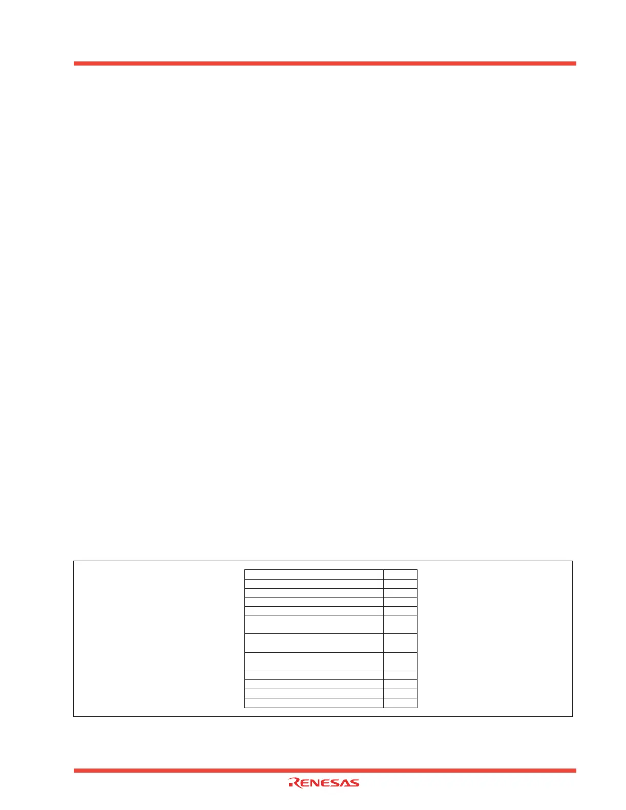
Figure 2.33 shows the memory map of Timer B-related registers. Figure 2.34 and Figure 2.35 show
Timer B-related registers.
Figure 2.33: Memory map of Timer B related registers
• The internal count source is counted See section 2.3.2.1
005A
16
Timer B0 interrupt control register TB0IC
005B
16
Timer B1 interrupt control register TB1IC
0380
16
Count start flag TABSR
U2BRG
0390
16
Timer B0 TB0
0391
16
0392
16
Timer B2 TB2
0393
16
0394
16
Timer B2 TB2
0395
16
039B
16
Timer B0 mode register TB0MR
039C
16
Timer B1 mode register TB1MR
039C
16
Timer B2 mode register TB2MR