Timer A
M30240 Group
Rev.1.00 Sep 24, 2003 Page 166 of 360
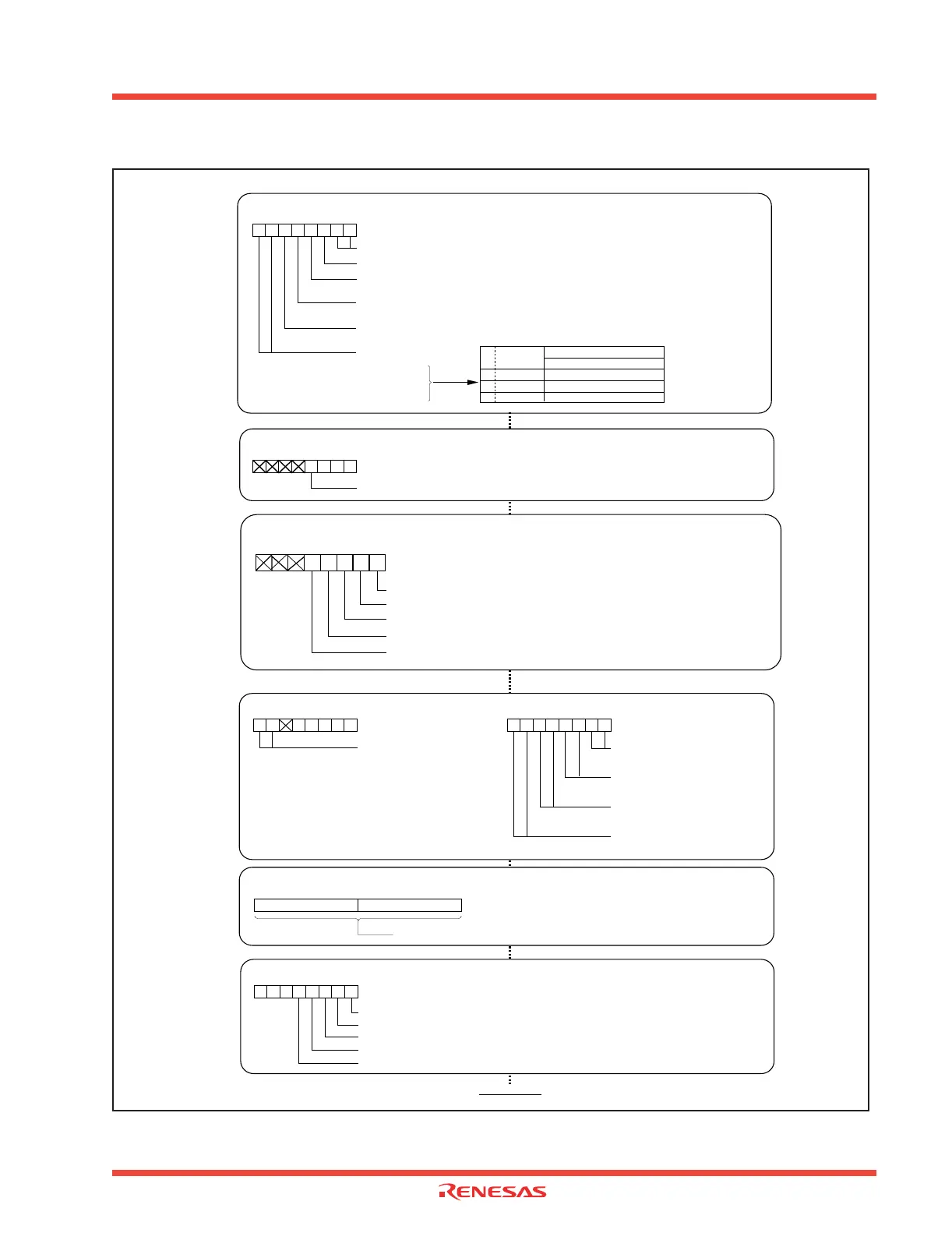
Figure 2.26: Set-up procedure of pulse width modulation mode, 16-bit PWM mode selected
Setting PWM pulse's “H” level width
Can be set to 0000
16
to FFFE
16
b7 b0
(b15) (b8)
b7 b0
Timer A0 register [Address 0387
16
, 0386
16
] TA0
Timer A1 register [Address 0389
16
, 0388
16
] TA1
Timer A2 register [Address 038B
16
, 038A
16
] TA2
Timer A3 register [Address 038D
16
, 038C
16
] TA3
Timer A4 register [Address 038F
16
, 038E
16
] TA4
Start count
Setting count starts flag
Count start flag [Address 0380
16
]
TABSR
Timer A0 count start flag
Timer A1 count start flag
Timer A2 count start flag
Timer A3 count start flag
Timer A4 count start flag
b7 b0
Setting event/trigger select bit
One-shot start flag [Address 0382
16
]
ONSF
Timer A0 event/trigger select bit
0 0 :
Input on TA0
IN
is selected (Note 2)
b7 b6
b7 b0 b7 b0
Timer A1 event/trigger select bit
0 0 :
Input on TA1
IN
is selected (Note 2)
b1 b0
Timer A2 event/trigger select bit
0 0 :
Input on TA2
IN
is selected (Note 2)
b3 b2
Timer A3 event/trigger select bit
0 0 :
Input on TA3
IN
is selected (Note 2)
b5 b4
Timer A4 event/trigger select bit
0 0 :
Input on TA4
IN
is selected (Note 2)
b7 b6
Note 2: Set the corresponding port direction register to “0”.
Trigger select register [Address 0383
16
]
TRGSR
1
(Must
always be “1” in PWM mode)
Selecting PWM mode and functions
Timer Ai mode register (i=0 to 4) [Address 0396
16
to 039A
16
]
TAiMR (i=0 to 4)
External trigger select bit
1 : Rising edge of TAi
IN
pin's input signal (Note 1)
Selection of PWM mode
b7 b0
11111
16/8-bit PWM mode select bit
0 : Functions as a 16-bit pulse width modulator
b7 b6
Count source select bit
0 0 : f
1
0 1 : f
8
1 0 : f
32
1 1 : Reserved
Trigger select bit
1 : Selected by event/trigger select register
0
Count source period
f(X
IN
) : 12MH
Z
b7 b6
Count
source
83.3ns
667ns
2.67µs
00
01
10
f
1
f
8
f
32
Note 1: Set the corresponding port direction
register to “0”.
Clearing timer Ai interrupt request bit
Timer Ai interrupt control register [Address 0055
16
to 0059
16
]
TAiIC (i=0 to 4)
Interrupt request bit
b7 b0
0
Refer to 'Precaution for Timer A (pulse width modulation mode)'
Start count
Setting the TAi
OUT drive capacity
Timer A output drive capacity register
[Address 03FB16]
TADR
Timer A0
OUT
drive capacity
Timer A1
Timer A2
Timer A3
Timer A4
b7 b0
OUT
drive capacity
OUT
drive capacity
OUT
drive capacity
OUT
drive capacity
 Loading...


