Programmable I/O Ports
M30240 Group
Rev.1.00 Sep 24, 2003 Page 283 of 360
2.13.1.6 I/O functions of built-in peripheral devices
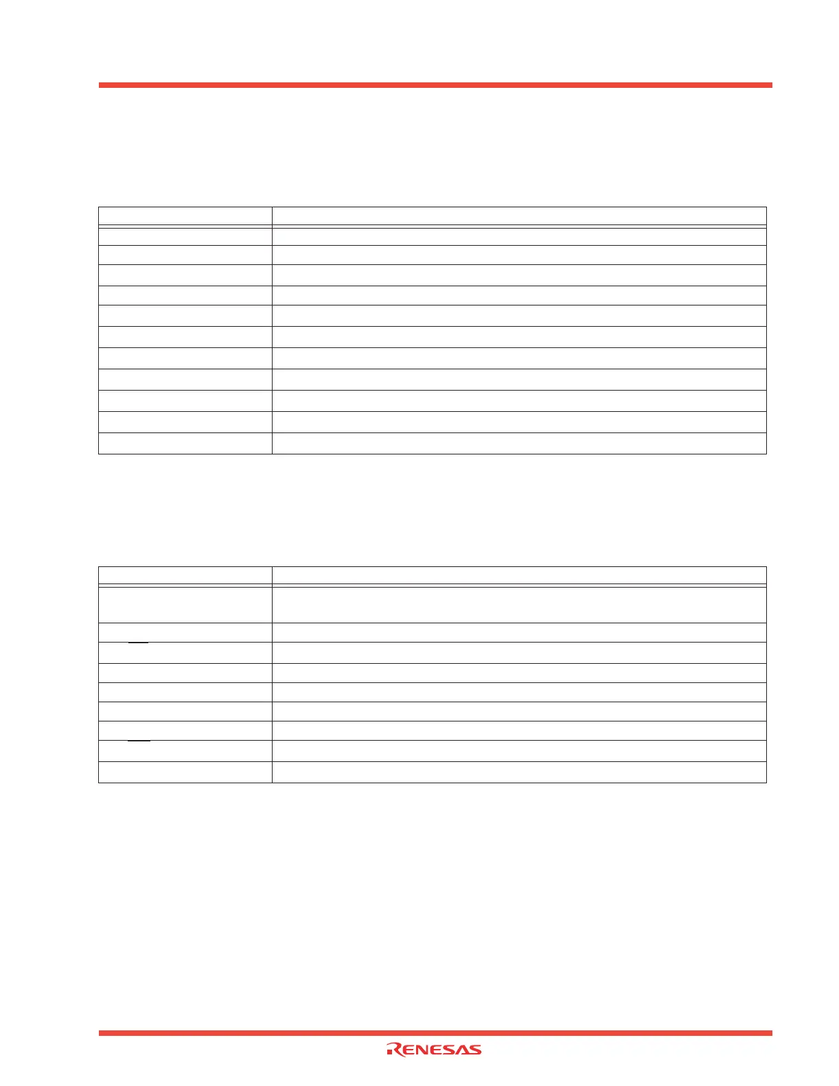
Table 2.41 shows the relationship between ports and I/O functions of built-in peripheral devices.
Table 2.43: Port and I/O function relationshipsPort and I/O function relationships
2.13.1.7 Examples of connection of non-used pins
Table 2.42 contains examples of connecting non-used pins. Make suitable changes and perform
sufficient evaluation in compliance with your application.
Table 2.44: An example of unused pin connections
Note 1: If setting these pins in output mode and opening them, ports are in input mode until switched into output mode by
use of software after reset. This the voltage levels of the pins becomes unstable and there can be instances where
the power source current increases while the ports are in input mode.
In view of an instance where the contents of the direction registers change due to a runaway generated by noise
or other causes, setting the contents of the direction register periodically by use of software increases program reli-
ability.
Note 2: When an external clock is input to the Xin pin.
Port Internal peripheral device I/O pins
P0 to P1 Key input interrupt function input pins
P2 LED driver pins
P3
7
Clock out pin
P6 I/O pins for serial I/O communication
P7
0
to P7
3
I/O pins for serial I/O communication / Timer A I/O pins
P7
4
to P8
1
Timer A I/O pins
P8
2
, P8
4
I/O pins for external interrupt
P8
3
USB Attach/Detach pin
P8
6
USB Start of Frame interrupt pin
P8
7
A-D trigger input pin
P10
A-D converter input pins
Pin name Connection
Ports P0 to P10 (excluding P8
3
,
P8
5
, P8
6
)
After setting to input mode, connect every pin to Vss or Vcc via a resistor; or after setting to output
mode, leave these pins open (Note 1)
Xout Open (Note 2)
P8
5
/NMI
Connect to Vcc via a resistor
AVcc Connect to Vcc
AVss, Vref, BYTE Connect to Vss
USB D+, USB D- Open
ExtCap Connect to Vcc (when DC-DC converter is disabled)
P8
6/
SOF
After setting to output mode in normal operation, leave this pin open
P8
3/
ATTACH
After setting to output mode in normal operation, leave this pin open
 Loading...


