Universal Serial Bus
M30240 Group
Rev.1.00 Sep 24, 2003 Page 315 of 360
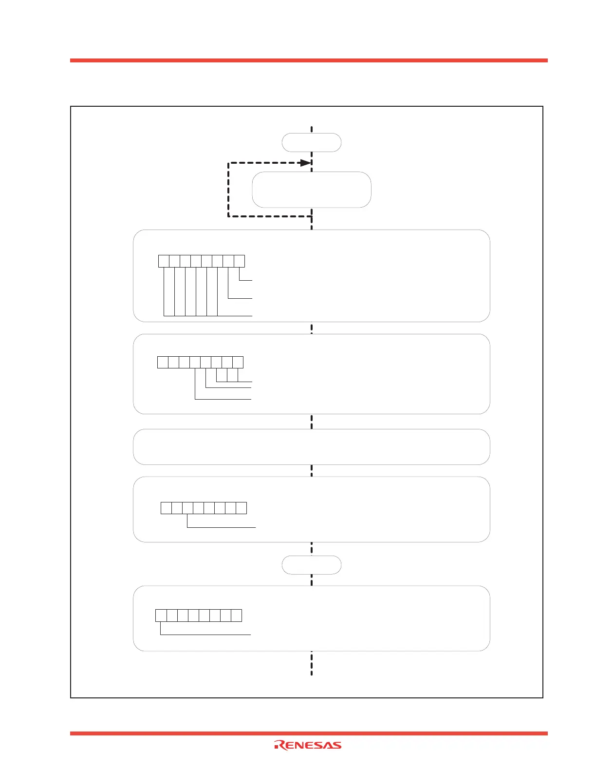
Figure 3.28: Initializing USB Function Control Unit (2)
Selecting the Attach/Detach Register
000
USB Attach/Detach Register Address
USBAD 001F
16
Port P8
3
Control Bit
0 : Standard
1 : Use Port 8
3
as the curent supply termial to D+
Attach/Detach Selection Bit
0 : Detach
1 : Attach
Reserved Bit
Enable DC-DC Driver
USB Clock Enable
USB Control Register Address
USBC 000C
16
USB Clock Enable Bit
1 : Clock supply enable 48 MHz
EXTCAP Terminal (or supply 3.3V to the ATTACH terminal (Note 1)) Stabilize.
Note 1: Wait requires (C + 1) ms. C is the capacity (µF) of the capacitor that is connected to the EXTCAP terminal.
Continued from previous page
Continued on next page
00
USB Control Register Address
USBC 000C
16
Reserved Bit
USB transceiver current mode selection bit
0 : High Operation
USB transceiver voltage converter enable bit
1 : Enabled
10 000
1
b7 b0
b7 b0
b7 b0
0
USB Function Control Unit Enable
USB Control Register Address
USBC 000C
16
USB Enable Bit
b7 b0
1
2ms wait
Check Frequency synthesizer
locked state bit
Wait 4 cycles
 Loading...


