EPROM version
M30240 Group
Rev.1.00 Sep 24, 2003 Page 354 of 360
5.2.3.1 Electrical Characteristics.
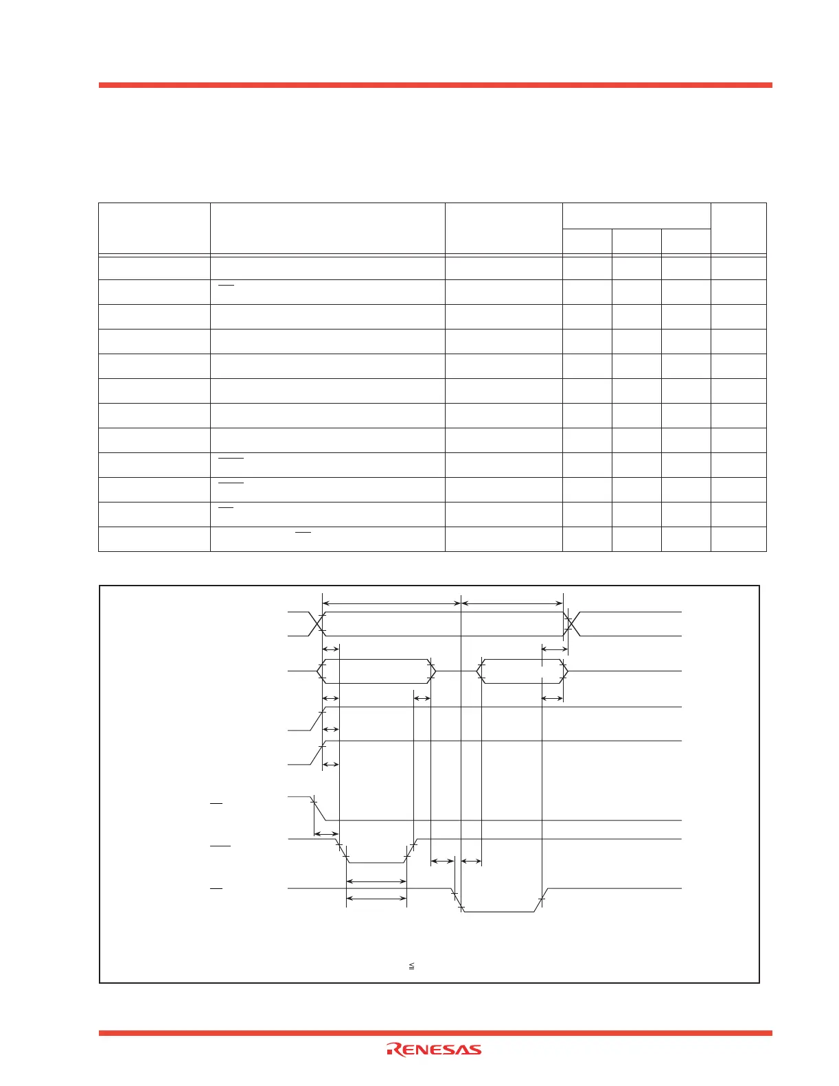
Figure 5.4: Programming timing diagram
Table 5.4: AC Electrical characteristics (Ta = 25 ± 5°C, Vcc = 6 ± 0.25V, Vpp = 12.5 ± 0.3V unless
otherwise noted)
Symbol Parameter
Measuring
Condition
Limits
Unit
Min. Type Max.
tAS Address setup time 2 µs
tOES OE
setup time 2 µs
tDS Data setup time 2
µs
tAH Address hold time 0
µs
tDH Data hold time 2
µs
tDFP Output enable to output float delay 0 130 ns
tVCS Vcc setup time 2
µs
tVPS Vpp setup time 2
µs
tPW PGM
pulse width 0.19 .02 0.21 ms
tOPW PGM
over program pulse width 0.19 5.25 ms
tCES CE
setup time 2 µs
tOE Data valid from OE
150 ns
tVCS
tVPS
tDS tDH tDFP
tAS
tOPW
tPW
tAH
VerifyProgram
Data set
Data output valid
V
IH
V
IL
V
IH
/V
OH
V
IL
/V
OL
V
PP
V
CC
V
CC
+ 1
V
CC
V
IH
V
IL
V
IH
V
IL
Address
Data
V
PP
V
CC
CE
OE
tOES tOE
V
IH
V
IL
PGM
tCES
Switching characteristics test conditions
Input voltage : V
IL
= 0.45V, V
IH
= 2.4V
Input signal rising / falling time (10 %to 90%) : 20ns
Referrence voltage in timing test : Input / output “L” = 0.8V, “H” = 2V
 Loading...


