DMAC
M30240 Group
Rev.1.00 Sep 24, 2003 Page 64 of 360
Number of transfer cycles per transfer unit = Number of read cycles x j + Number of write cycles x k
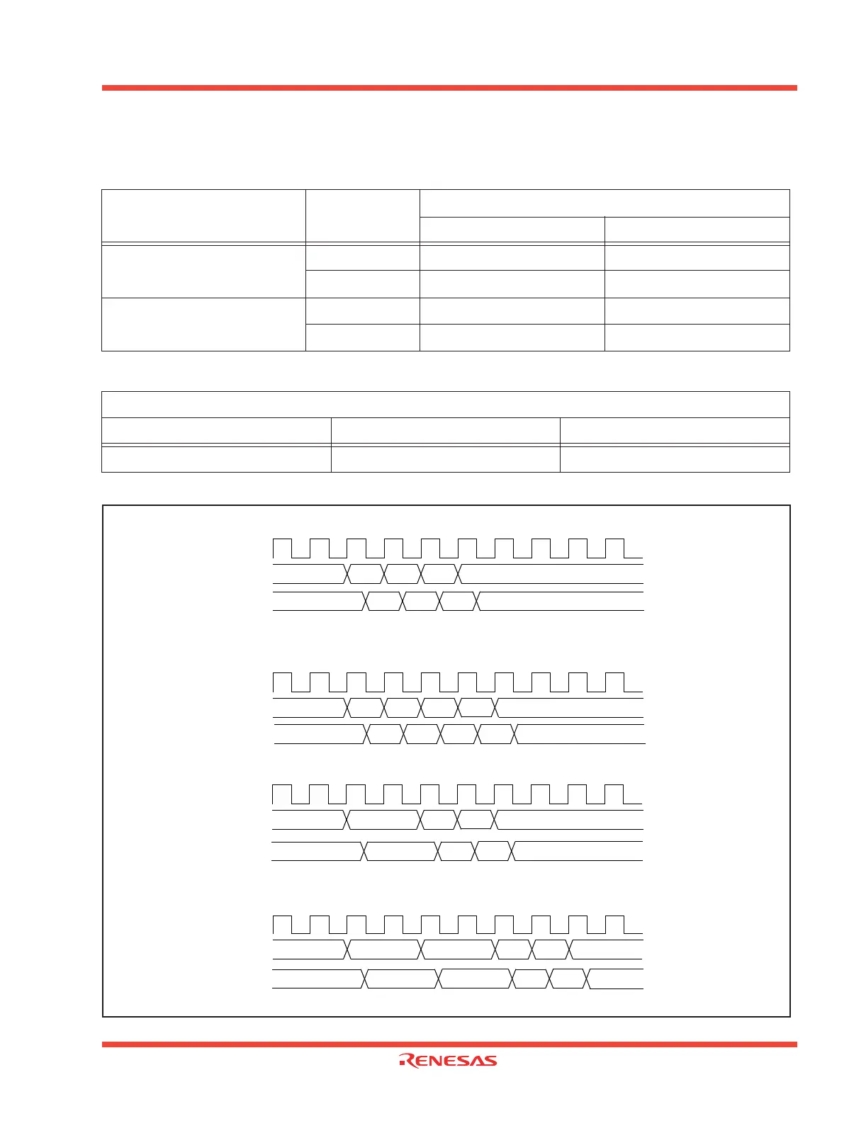
Figure 1.57: Example of the transfer cycle for a source read
Table 1.16: Number of DMAC transfer cycles
Transfer unit Access address
Single-chip mode
Number of read cycles Number of write cycles
8-bit transfers (DMBIT=”1”)
Even 1 1
Odd 1 1
16-bit transfers (DMBIT=”0”)
Even 1 1
Odd 2 2
Table 1.17: Coefficients j,k
Internal memory
Internal ROM/RAM No wait Internal ROM/RAM with wait SFR area
122
Internal
clock Φ
Address
bus
Data
bus
CPU use
CPU use CPU use
CPU useSource
Source
Destination
Destination
(1) 8-bit transfers
16-bit transfers from even address and the source address is even.
Address
bus
Data
bus
CPU use
CPU use CPU use
CPU useSource
Source
Destination
Destination
(3) One wait is inserted into the source read under the conditions in (1)
Address
bus
Data
bus
CPU use
CPU use
CPU use
CPU useSource
Source
Destination
Destination
Source + 1
Source + 1
(2) 16-bit transfers and the source address is odd
Address
bus
Data
bus
CPU use
CPU use CPU use
CPU useSource
Source
Destination
Destination
Source + 1
Source + 1
(4) One wait is inserted into the source read under the conditions in (2)
Note : The same timing changes occur with the respective conditions at the destination as at the source.
(When 16-bit data is transfferred on an 8-bit data but, there are two destination write cycles.)
Internal
clock Φ
Internal
clock Φ
Internal
clock Φ
 Loading...


