RL78/F13, F14 CHAPTER 24 RESET FUNCTION
R01UH0368EJ0210 Rev.2.10 1550
Dec 10, 2015
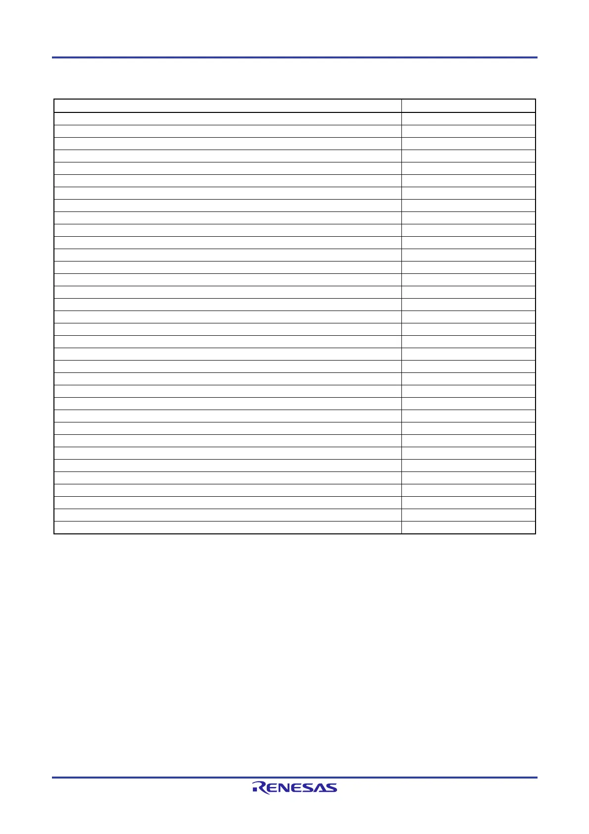
Table 24-2. States of Hardware After Acceptance of a Reset (4/4)
Hardware After Acceptance of a Reset
Note 1
LIN channel select register (LCHSEL) 00H
LIN/UART baud rate prescaler 0 register (LBRP00/LBRP10) 00H
LIN/UART baud rate prescaler 1 register (LBRP01/LBRP11) 00H
LIN self test control register (LSTC0/LSTC1) 00H
UART standby control register (LUSC0/LUSC1) 00H
LIN/UART mode register (LMD0/LMD1) 00H
LIN break field configuration register/UART configuration register (LBFC0/LBFC1) 00H
LIN/UART space configuration register (LSC0/LSC1) 00H
LIN wakeup configuration register (LWUP0/LWUP1) 00H
LIN interrupt enable register (LIE0/LIE1) 00H
LIN/UART error detection enable register (LEDE0/LEDE1) 00H
LIN/UART control register (LCUC0/LCUC1) 00H
LIN/UART transmit control register (LTRC0/LTRC1) 00H
LIN/UART mode status register (LMST0/LMST1) 00H
LIN/UART status register (LST0/LST1) 00H
LIN/UART error status register (LEST0/LEST1) 00H
LIN/UART data field configuration register (LDFC0/LDFC1) 00H
LIN/UART ID buffer register (LIDB0/LIDB1) 00H
LIN checksum buffer register (LCBR0/LCBR1) 00H
UART data buffer 0 register (LUDB00/LUDB10) 00H
LIN/UART data buffer 1 register (LDB01/LDB11) 00H
LIN/UART data buffer 2 register (LDB02/LDB12) 00H
LIN/UART data buffer 3 register (LDB03/LDB13) 00H
LIN/UART data buffer 4 register (LDB04/LDB14) 00H
LIN/UART data buffer 5 register (LDB05/LDB15) 00H
LIN/UART data buffer 6 register (LDB06/LDB16) 00H
LIN/UART data buffer 7 register (LDB07/LDB17) 00H
LIN/UART data buffer 8 register (LDB08/LDB18) 00H
UART operation enable register (LUOER0/LUOER1) 00H
UART option register 1 (LUOR01/LUOR11) 00H
UART transmit data register (LUTDR0/LUTDR1) 0000H
UART receive data register (LURDR0/LURDR1) 0000H
UART wait transmission data register (LUWTDR0/LUWTDR1) 0000H
CAN-related registers See Table 3-6.
Notes 1. During reset signal generation or oscillation stabilization time wait, only the PC contents among the hardware
statuses become undefined. All other hardware statuses remain unchanged after reset.
2. The reset value differs for each chip.
3. The timer RD SFRs are undefined when FRQSEL4 = 1 in the user option byte (000C2H/010C2H) and TRD0EN
= 0 in the PER1 register. If it is necessary to read the initial value, set f
CLK to fIH and TRD0EN = 1 before reading.
4.
If the AMPM bit (bit 3 of the real-time clock control register 0 (RTCC0)) is set to 1 after a reset, the setting of the
hour count register (HOUR) becomes 00H.
5. The values depend on the source of the reset as shown in Table 24-3.
6. The reset value of the LVIS register varies depending on the reset source and the setting of the option byte.
7.
The reset value of WDTE is determined by the option byte setting.
8. Only in the RL78/F14.
Remark The special function register (SFR) mounted depends on the product. See 3.1.4 Special function register (SFR)
area and 3.1.5 Extended special function register (2nd SFR: 2nd Special Function Register) area.
 Loading...


