RL78/F13, F14 CHAPTER 2 PIN FUNCTIONS
R01UH0368EJ0210 Rev.2.10 62
Dec 10, 2015
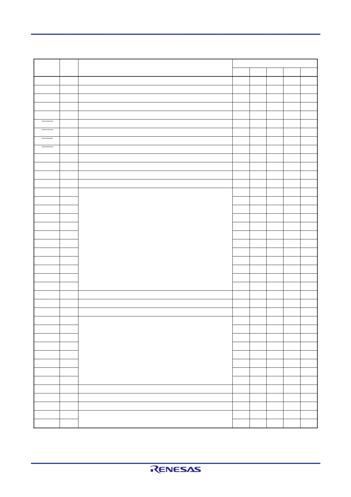
Table 2-3. List of RL78/F13 (CAN and LIN incorporated) Pins Other than Port Pins (3/4)
Pin
Function
I/O Function Pin Count
80-pin 64-pin 48-pin 32-pin 30-pin
SI11 Input Serial data input to CSI11
SO00 Output Serial data output from CSI00
SO01 Output Serial data output from CSI01
SO10 Output Serial data output from CSI10
SO11 Output Serial data output from CSI11
SSI00 Input Slave select input to CSI00 (SPI00)
SSI01 Input Slave select input to CSI01 (SPI01)
SSI10 Input Slave select input to CSI10 (SPI10)
SSI11 Input Slave select input to CSI11 (SPI11)
CRXD0 Input Serial data input to CAN
CTXD0 Output Serial data output from CAN
LRXD0 Input Serial data input to LIN
LTXD0 Output Serial data output from LIN
INTP0 Input External interrupt input
INTP1 Input
INTP2 Input
INTP3 Input
INTP4 Input
INTP5 Input
INTP6 Input
INTP7 Input
INTP8 Input
INTP9 Input
INTP10 Input
INTP11 Input
PCLBUZ0 Output Clock output/buzzer output 0
RESOUT Output Reset output
STOPST Output STOP status output
SNZOUT0 Output SNOOZE status output
SNZOUT1 Output
SNZOUT2 Output
SNZOUT3 Output
SNZOUT4 Output
SNZOUT5 Output
SNZOUT6 Output
SNZOUT7 Output
RTC1HZ Output Real-time clock correction clock (1 Hz) output
EXCLK Input External clock input for main system clock
EXCLKS Input External clock input for subsystem clock
X1 Resonator connection for main system clock
X2
 Loading...


