Technical Bulletin PAGE: 2/3
Note:
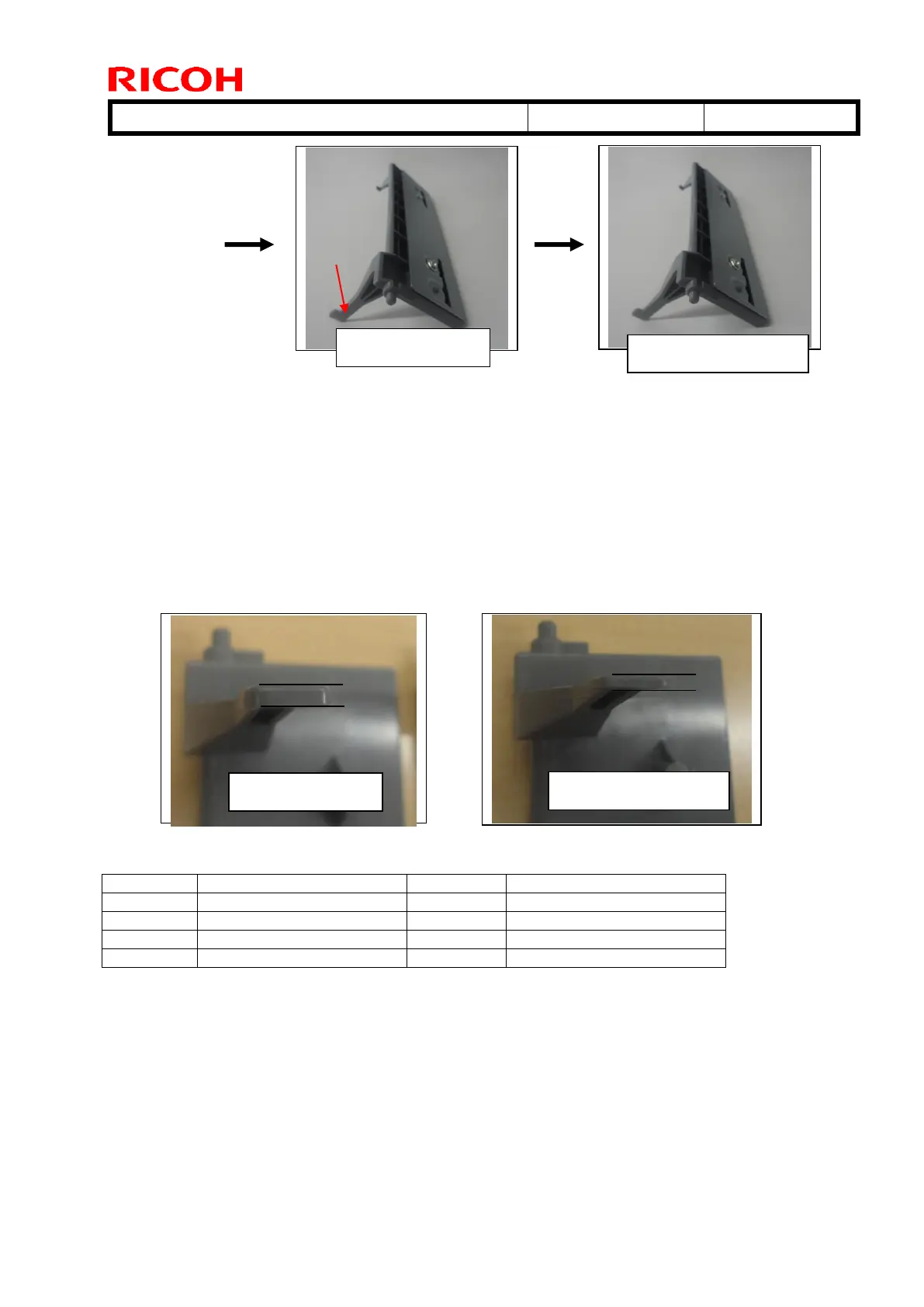
- [A] was modified to [B] to ensure that the trailing edge of the paper does not hit the end
fence guide, which can cause the fence to open and prevent the tray from rising. The paper
guide was removed and a metal plate [F] was added. Two spacers were added to correct the
position of the tray set sensor actuator [H] (See “Attaching spacers for parts [B]/[C]”
below).
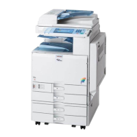
- [B] was modified to [C] because portion [G] of the metal plate was unnecessary (and was
deleted).
- [C] was modified to [D] to ensure that the actuator [H] can move correctly into the tray set
sensor. To do this, the thickness of the actuator was decreased from 2mm to 1mm. For this
reason, the spacers used for parts [B]/[C] are not needed.
Cut-in S/N for part [D]:
Temporary
End fence #2 [C]
Permanent end
fence: D1357510 [D]
Permanent end
fence: D1357510 [D]
Temporary
end fence #2 [C]