No parameter of Latching relay can be set/modified in parameter mode .
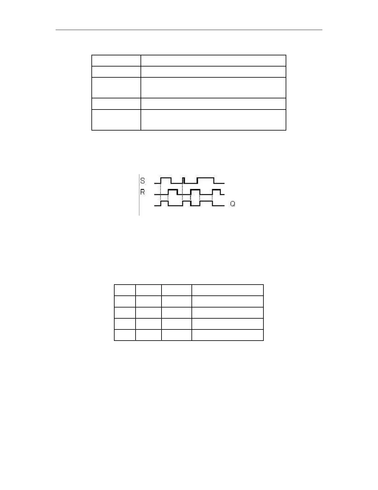
Timing diagram
Description of the function
The latching relay represents a simple binary memory logic. The output value depends on the input states
and the previous status at the output.
Logic table of the latching relay:
When retentivity is enabled, the output signal corresponds with the signal status prior to the power failure.
Set output Q with a signal at input S (Set).
Reset output Q with a signal at input R (Reset). Output Q is
reset if S and R are both set (reset has priority over set).
Retentivity set (on) = the status is retentive in memory.
Q is set with a signal at input S and remains set until it is
reset with signal at input R.