17 : type code (17 means the Analog flag)
08 : length field = number of bytes of the analog flag
01 c2 00 00 02 26 00 00 : analog flag value (AF1= 01 c2 , AF2 = 00 00, AF3= 02 26,AF4= 00 00)
07 01 04
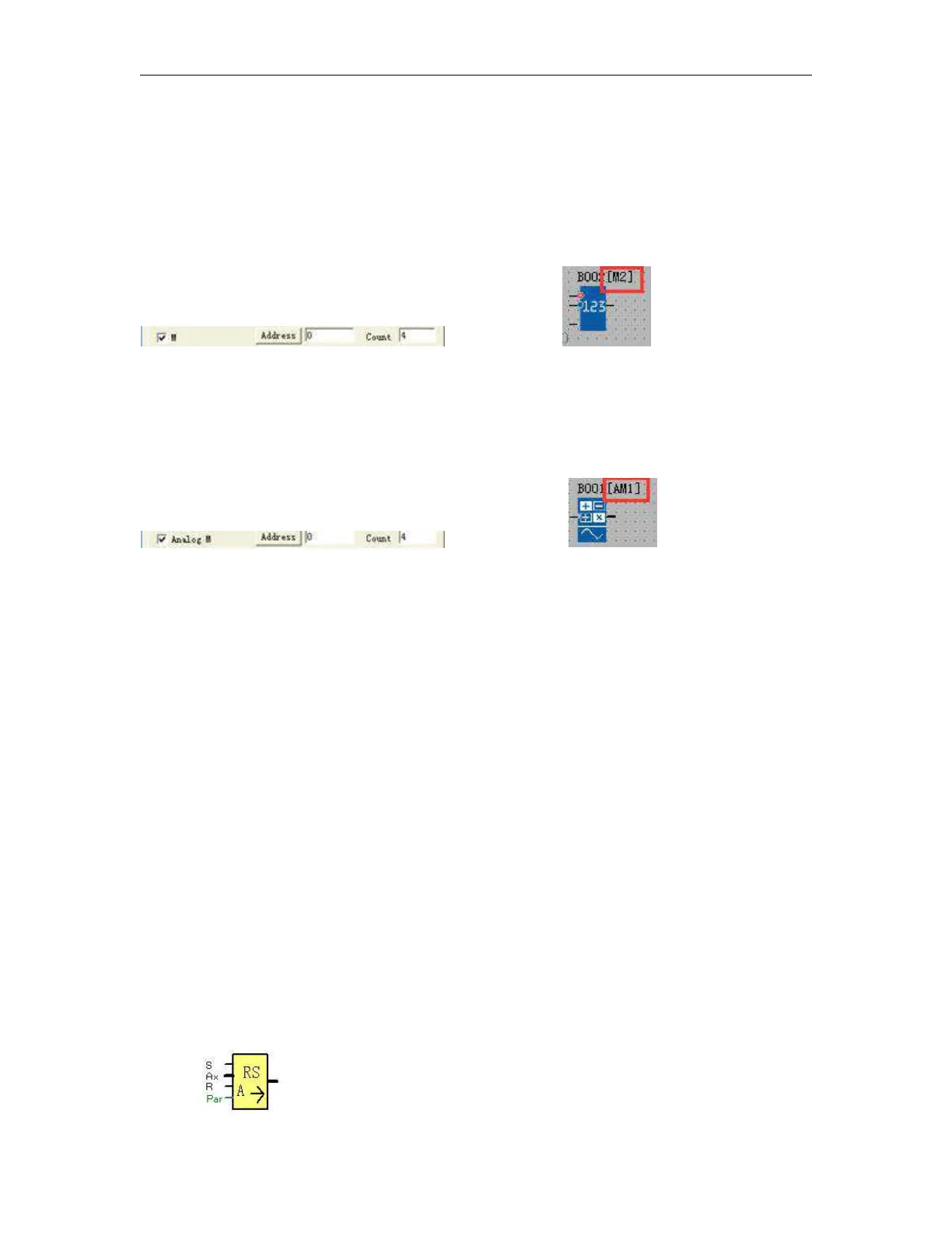
07 : type code (07 means the M status)
01 : length field = number of bytes of M(Function block status(1/0))
04: status of the M (M1=0,M2=10,M3=1,M4=0)
0d 08 00 00 00 00 00 00 01 c2
0d : type code (0d means the AM value)
08 : length field = number of bytes of AM
00 00 00 00 00 00 01 c2: AM value (AM1=00 00,AM2=00 00,AM3=00 00,AM4=01 c2)
The server end need do response like this:
00 00 00 00 00 02 01 8b
You can use the above fixed data as the response for the customize MODBUS.
So if the "Trg" input keeps high, the the output will be high also after the EXM get the above correct response.
Note:The command format is based on the standard Modbus TCP. Please refer to the technical file "Modbus
TCP communication protocol" for detail if require.
6.5.35 Data latching relay