6.5.28 Pulse Width Modulator (PWM)
Short Description:
The Pulse Width Modulator (PWM) instruction modulates the analog input value Ax to a pulsed digital output
signal. The pulse width is proportional to the analog value Ax.
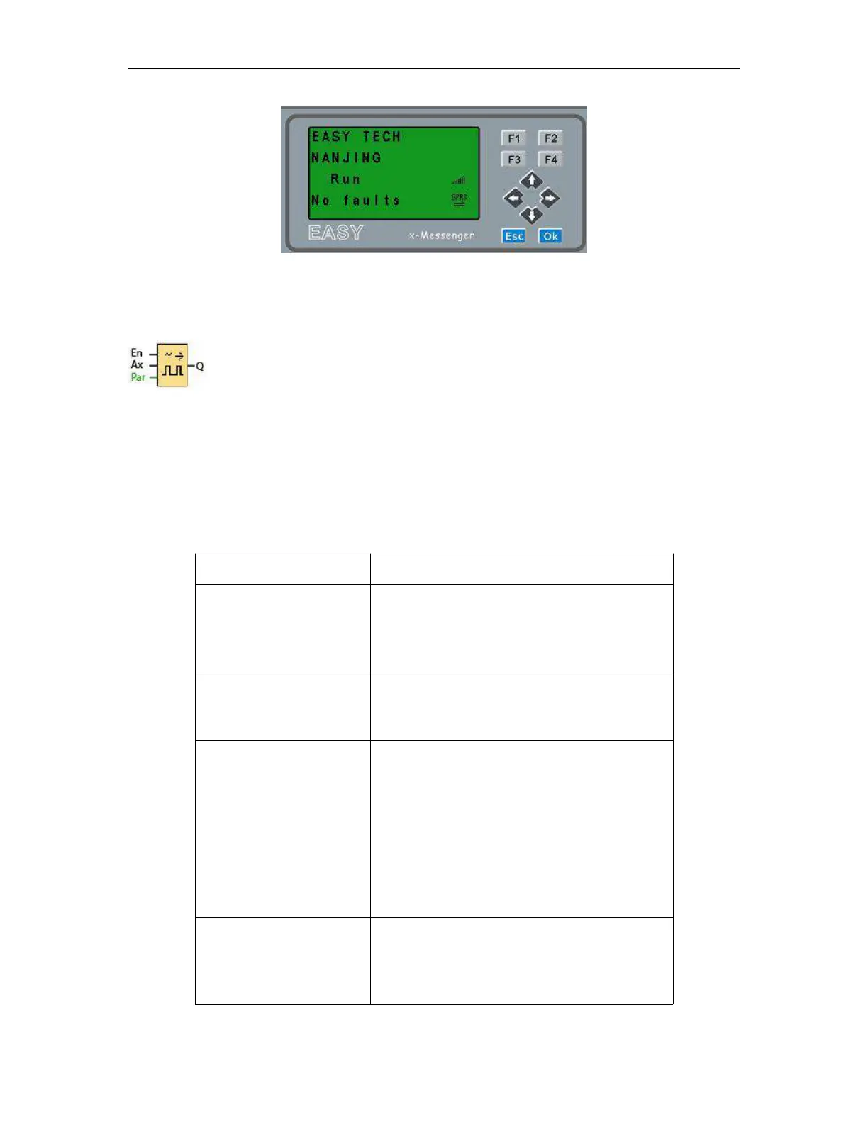
A positive edge (0 to 1 transition) at
input En enables the PWM function
block.
Analog signal to be modulated to a
pulsed digital output signal.
A: Gain
Range of values: +- 10.00
B: Zero offset
Range of values: +- 10,000
PT: Periodic time over which the digital
output is modulated
p: Number of decimals
Range of values: 0, 1, 2, 3
Q is set or reset for the proportion of each time
period according to the proportion of the
standardized value Ax to the analog value range.