MASTER STC
USER MANUAL
16
RF INPUT SIGNAL TYPE (CABLE OR OFF AIR)
Using the Standard Navigation Mode, highlight the AUTOMEMORY item select the RF
band, terrestrial analogue and digital, (TV ONLY) or cable (CATV).
8.4 SATELLITE RECEPTION SETUP
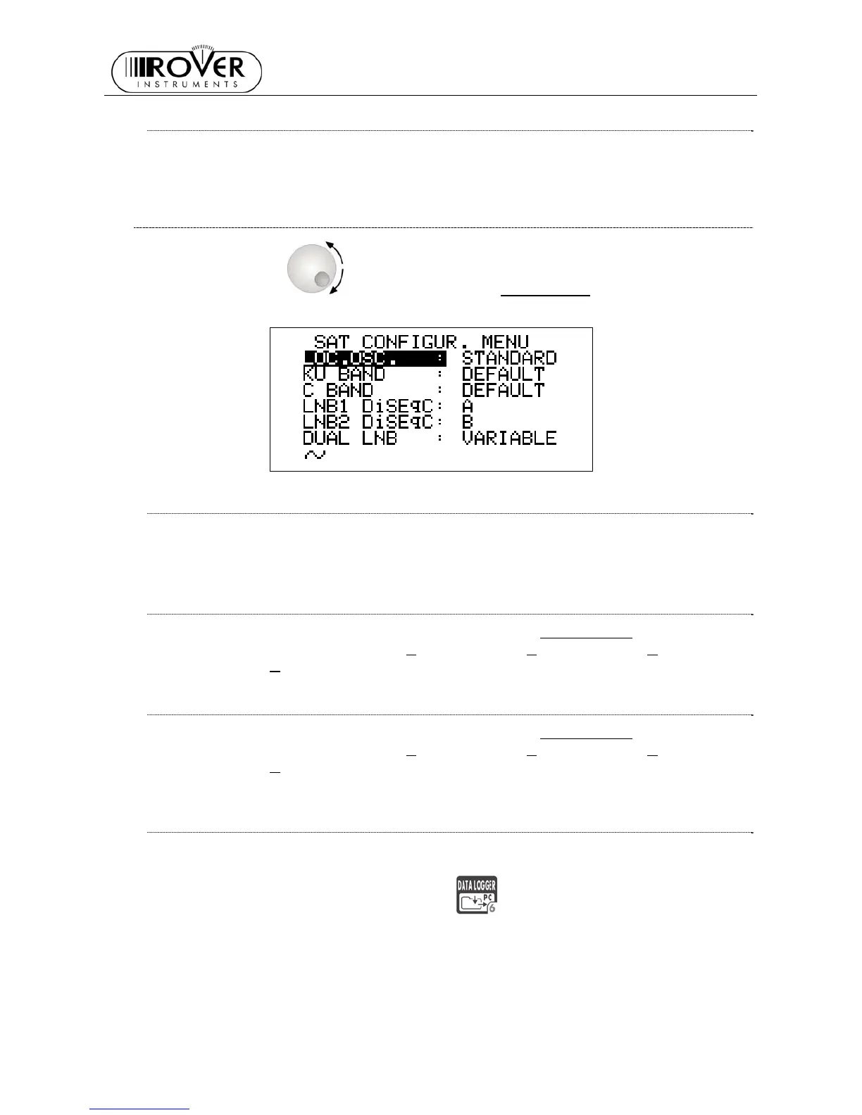
Rotate the encoder [D] to highlight the item SAT CONFIG, then press it to enter
the selection menu.
LOCAL OSCILLATOR SETUP
Using the Standard Navigation Mode, highlight the item LOC.OSC. and select
STANDARD (signal coming directly from the antenna, down-conversion required) or
0MHz(IF) (intermediate frequency signal, e.g. from a LNB).
LNB 1 ALLOWED POLARIZATION SETUP
Using the Standard Navigation Mode, highlight the item LNB1 DiSEqC and select the
required polarization for the LNB1 (A
=4 polarizations, B=8 polarizations, C=12
polarizations, D
=16 polarizations).
LNB 2 ALLOWED POLARIZATIONS SETUP
Using the Standard Navigation Mode, highlight the item LNB1 DiSEqC and select the
required polarization for the LNB2 (A
=4 polarizations, B=8 polarizations, C=12
polarizations, D
=16 polarizations).
SINGLE-CABLE SCR COMPLIANT LNB OR MULTISWITCH SETUP : SAT SCR
MENU
This function allows the user to check and manage single cable multi-users satellite
installations.
Press and hold for 2s the DATA LOGGER
[6] key. The LCD [C] will display the
SAT SCR configuration menu: