MASTER STC
USER MANUAL
25
11 PERFORMING MEASURES: MEAS
The MASTER STC is equipped with one LCD [C] display; at the same time, all the
measurement values can be displayed on a high brightness screen and their reading is
immediate and intuitive, also under direct sunlight and in any weather condition.
Refer to the Chapter 10 SIGNAL TUNING: PLAN at page 20 to tune the desired channel.
11.1 THE SELECTED CHANNEL CARRIERS ON AN ANALOGUE TV
SIGNAL
VIDEO SIGNAL PEAK LEVEL MEASUREMENT
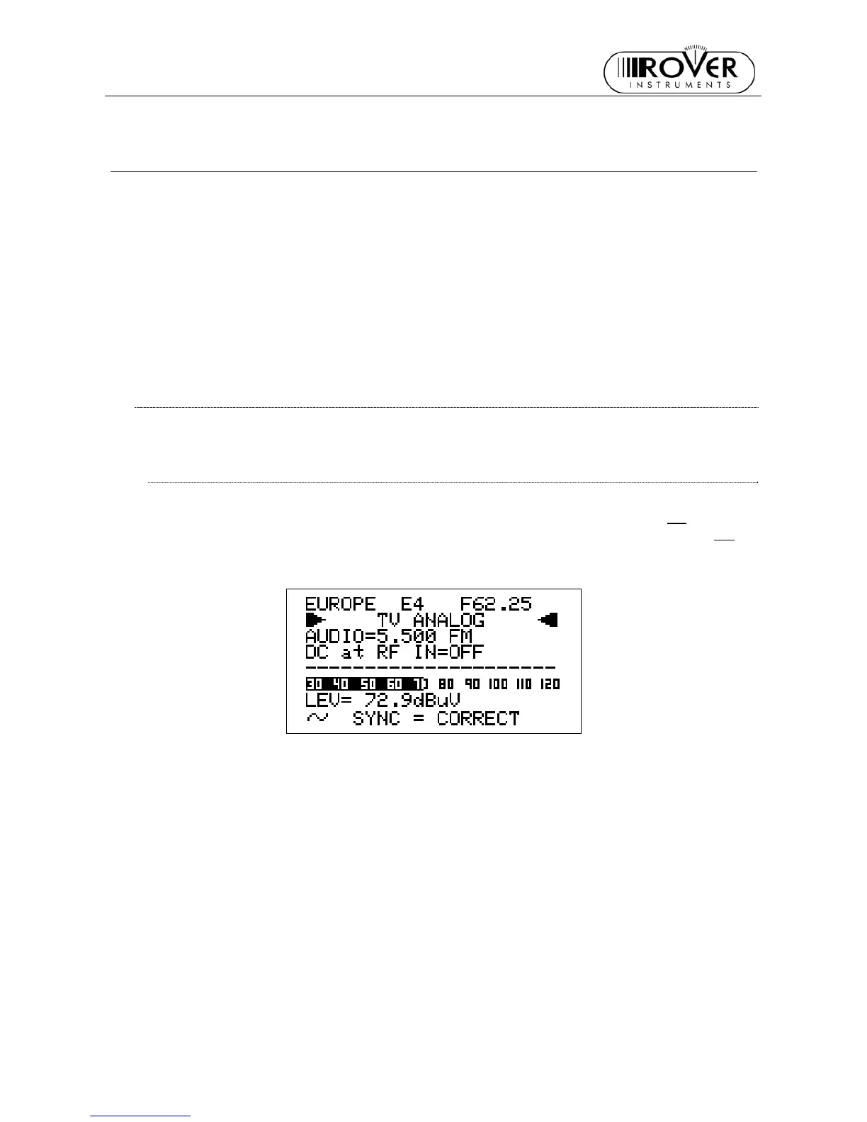
The LCD second row (from the top) displays “TV ANALOG”.
On the bottom right side of the screen, the letter “T” will be displayed above the TV
icon
marked on the display frame, and a black filled quadrangle will be displayed above the AN
icon marked on the display frame.
The current video signal peak level will be displayed on the bottom of the screen, together
with the relevant measurement unit. The video signal peak level real time value is also
displayed on a level bar with peak level memory.
The last line in the display will show the video sync status.