MASTER STC
USER MANUAL
54
LNB 2: SATELLITE SETUP.
Using the Standard navigation Mode, select the satellite (satellite name) or the
Transponder Memory Plan (PLAN) to which the LNB2 has to be aligned.
Right to the satellite name or, resp. the Transponder Memory Plan, the reference
transponder for the LNB2 alignment is displayed.
If required, use the Standard Navigation Mode to select a different reference
transponder.
DISH ALIGNMENT & FINE DISH ALIGNMENT
Once selected the desired satellites, the LCD will display the Noise Margin and the
Quality Test results (FAIL, MARGIN, PASS) for each LNB. Each Noise Margin value
(LNB1 and LNB2) will be also displayed on a level bar with peak level memory.
Move the antenna dish till you get the maximum Noise Margin value on both LNB at
the same time. The peak level memory of each level bar displays a vertical bar
showing the maximum Noise Margin level reached by the relevant LNB while pointing.
In some cases it won’t be possible to maximize the Noise Margin value for both LNBs,
depending on the signal receiving conditions. In this case the antenna should be set to
get the best compromise between the Noise Margin value of the two LNBs.
Press once and release the MEAS [5] key to quit this function.
17.3 POINTING AND MOVING A MOTORIZED DISH (DiSEqC MOTOR)
Select the satellite (proceed as described in Chapter 18.1 EXPLORING ALL THE
TRANSPONDERS OF A SATELLITE at page 56) or the transponder included in the
satellite to which the antenna must be aligned (refer to the paragraph 18.2 MANUALLY
TUNING THE TRANSPONDER at page 57).
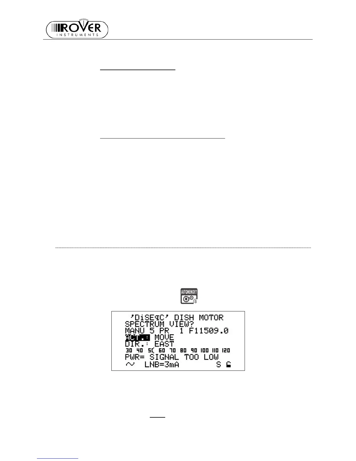
Press and hold for 2s the AUTOMEMORY
[8] key. The LCD will display:
The LCD third row from the top displays (left to right): the selected satellite name (or the
Transponder Channel Plan), the selected transponder and the relevant frequency value.
The LCD bottom rows display (bottom to top, left to right): the name of the selected
bouquet, the encryption system in use, the Noise Margin value (also displayed on the level
bar with peak memory level), and the result of the Quality Test.
In the previous screenshot, the ACT.:
item is highlighted: this item indicates the command
which will be sent to the motorized antenna.