MASTER STC
USER MANUAL
56
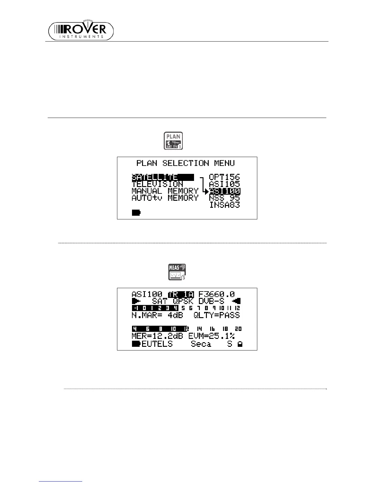
The LCD second row displays (left to right) the selected Satellite or the selected
Transponder Memory Plan, the currently tuned transponder and the relevant frequency
value. The frequency value can be modified using the encoder [D].
The two bottom rows display the Noise Margin measurement (also on a level bar with peak
memory function) and the Quality Test result.
Press any key to quit this function. The buzzer function is active with digital signals ONLY
18 METER CONFIGURATION : PLAN
Connect the coax cable to the connector F [U] on the meter.
Press once and release the PLAN
[1] key.
18.1 EXPLORING ALL THE TRANSPONDERS OF A SATELLITE
Using the Standard Navigation Mode, highlight the item SATELLITE and select the required
satellite.
Press once and release the MEAS
[5] key.
The LCD first row displays (left to right) the selected satellite, the transponder and the
relevant frequency value.
CHANGING THE SATELLITE
Press once and release the PLAN [1] key. Highlight the item SATELLITE and select the
desired satellite. Press once and release the MEAS [5] key to return to the current
measurement screen.