MASTER STC
USER MANUAL
40
directly set while this measurement function is active.
ACTIVATE THE FULL BAND MAPPING
Select one channel ID in the band (VHF, UHF, or CATV) to be analyzed (refer to
Chapter 12.1 SURFING THE CHANNELS at page 38.
Press once and release the BARSCAN
[0] key. Depending on the selected
configuration a specific bar diagram will be displayed.
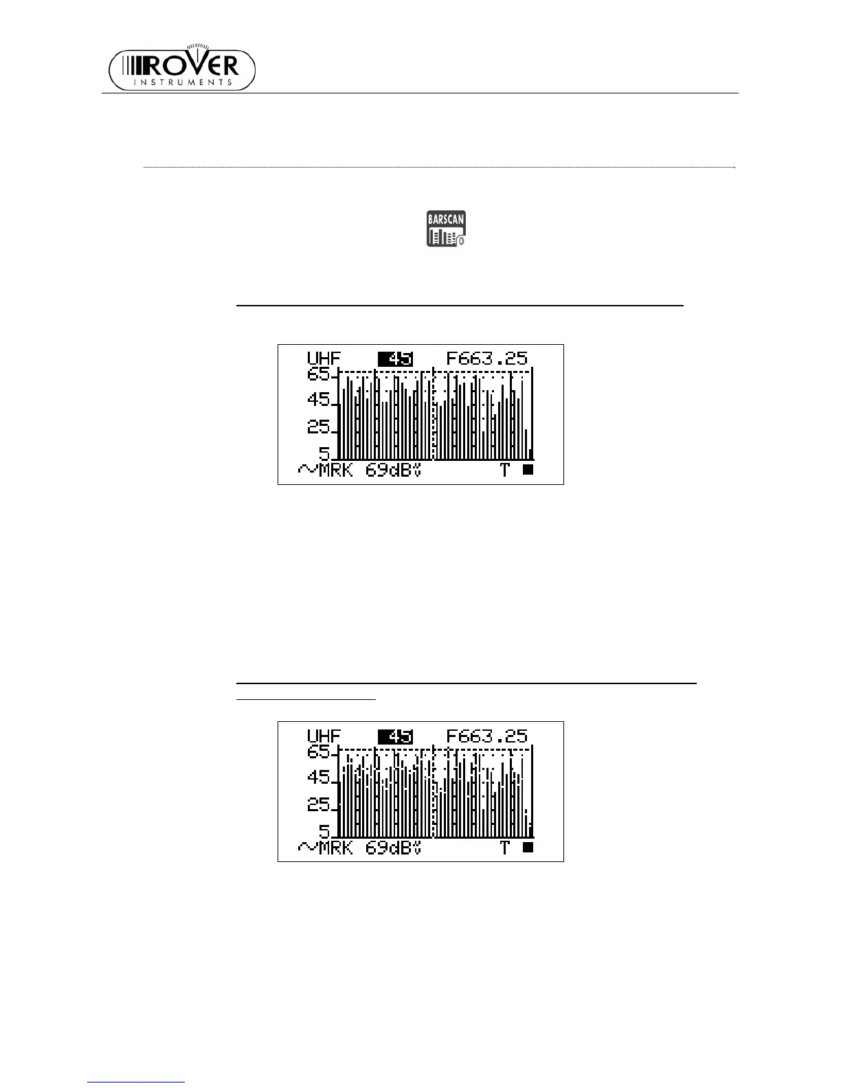
FULL BAND SIGNAL LEVEL ANALYSIS IN EACH CHANNEL (LEVEL)
The marker (the vertical dotted line) is positioned on the channel which is currently
displayed in the centre field of the LCD top row and whose frequency is displayed in
the LCD top right edge. The LCD bottom row displays the signal level measured in the
currently selected channel (MRK) together with the measurement unit currently set for
the meter. An horizontal dotted line shows the real time signal level value measured in
the currently selected channel.
FULL BAND AUDIO AND VIDEO PEAK LEVEL ANALYSYS INTO EACH
CHANNEL (AUD/VID)
Each black bar will contain a white pixel in it.
The overall height of each bar displays the video peak level measured in the relevant
channel.
The height of the bar segment between the x-axis and the above white pixel displays
the audio peak level measured in the relevant channel.
The marker (the vertical dotted line) is positioned on the channel which is currently
displayed in the centre field of the LCD top row and whose frequency is displayed in