MASTER STC
USER MANUAL
38
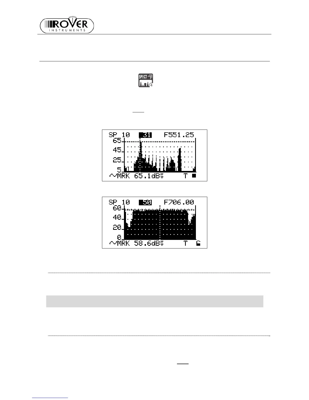
12 SPECTRUM ANALYZER MODE
Press once and release the SPECT
[4] key to display the spectrum of the current
signal.
In case the tuned signal is analogue, the marker will be positioned by default on the
frequency value corresponding to the analogue Video signal peak level. The relevant level is
displayed in the LCD bottom row (MRK
), together with the relevant measurement unit.
12.1 SURFING THE CHANNELS
Using the Standard Navigation Mode, highlight the currently tuned channel ID, then select
the desired channel ID.
WARNING: only the channels included into the channel plan (PLAN) currently in use
will be displayed.
Refer to Chapter 10 SIGNAL TUNING: PLAN at page 20
12.2 MOVING THE MARKER (FREQUENCY VALUE)
Using the Standard Navigation Mode, highlight the frequency item, then move the marker
position (current frequency value).
The meter LCD will at any time display the current frequency value (first row, top right) and
the relevant signal level measurement (bottom row, MRK
).