11
MPS4232
Section 2: Introduction
contains:
• All of the interface electrical connectors including the
Ethernet and Power connectors (which also supplies
RS-232 and external triggering leads)
• DC-DC power supply
• Processor and memory chips
• All Analog-to-Digital converters (one per sensor)
• 32 pressure sensors (4 per ceramic sck)
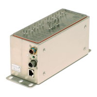
For added convenience and exibility, the pneumac inputs
on the MPS4000 series use removable headers. There
is one input pneumac connector on the MPS4232 that
house the 32 individual channel inputs for measurement
pressure (Px ports) and a single REF or reference port. The
pneumac connector is held on with three capve screws.
The removable input header allows for dierent input
headers to be installed or removed at any me. This allows
for dierent pneumac inputs, allowing for plumbing to
be removed from the module and swapped with another
module or plumbing harness, blanking caps for protecon,
or a calibraon input header for calibraons and valida-
ons. Please see Scanivalve’s Module Accessory Catalog for
a complete list of all pneumac input opons.
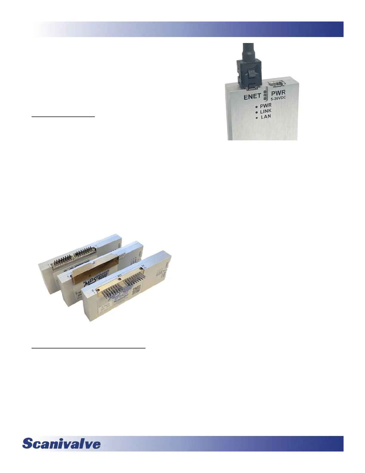
The MPS4232 has its power and Ethernet connecons
located on one end. The power connecon also serves as
an external trigger input and allows for a serial connec-
on. LEDs are posioned in a recessed cavity between the
two connectors to indicate power, link and acvity. Both
the power and the Ethernet connector are TE Connecvity
“Mini I/O” series but are polarized dierently to prevent
improper connecons. The connectors are latching to
prevent vibraon from loosening the connecons.