28
MPS4264
Section 4: Hardware
The MPS modules has several dierent pneumac connec-
ons. All pneumac inputs are located on the top of
the module. There are two basic groups of pneumac
connecons types on the module: pressure measurement
connecon and support connecons. All pneumac inputs
are through one removable header for easy plumbing
and system re-conguraon. The measurement ports
are located on the on the outer edge of the modules and
are idened as 1-32 on one pneumac header. These
32 input ports are directly connected to one of the indi-
vidual pressure transducers within the module. On the
same pneumac header as the measurement input ports
is the common reference port (REF). The REF port is used
for connecng the reference manifold to a known, stable
ambient pressure.
The 32 measurement input ports (or Px ports) are available
with 0.042” or 0.031” OD tubes. The tube REF input will
always be 0.063” OD.
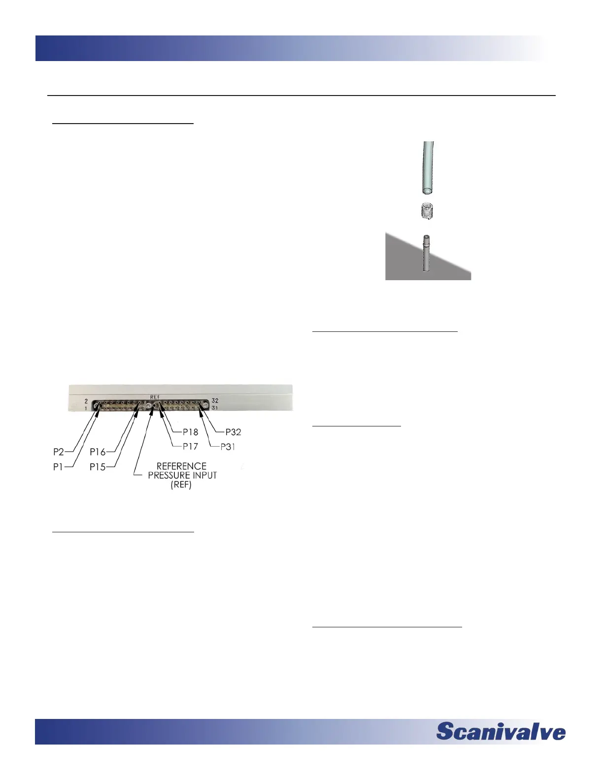
All pneumac connecons are 0.063”, 0.042” or 0.031”
OD stainless steel bulged tubulaons. These tubes are
designed to have a ght-ng plasc tube slid over the OD
of the tube. For all low pressure connecons (50psi and
less) the plasc tubing can simply be slid over the tubula-
on and the connecon is complete. When using Urethane
or Vinyl tubing for high pressure applicaons, a helical
spring clamp over the OD of the plasc tubing is recom-
mended. The clamp is slid over the tubing and located
around the apex of the bulged of the tubulaon. This helps
hold the plasc tubing in place and prevent leaks.
Installing the plasc tubing over the stainless steel tubing
can be done much easier by using Scanivalve’s special
“Tubing push-on tool” P/N: TPOTL-XXX. This tool is oered
in a variety of sizes to work for tubing from 0.031” to
0.125” OD.
Each MPS4232 scanner module has 32 pressure measure-
ment ports, or “Px” ports. They are labeled as 1-32.
Each of these ports are connected to a discrete pressure
transducer. If any Px ports are not being used, it is recom-
mended that they be covering to prevent dust or any debris
from clogging the port.
The ‘REF’ port es into a manifold that connects the back
side (or negave side) or all transducers together. During
most applicaons, the ‘REF’ port of low pressure modules
(below 15 psi) should be routed to a known, stable stac
locaon. Typically this “reference” locaon will be a wind
tunnel stac port, a stac barrel or in ight test applicaons
the aircra stac system. This ensures that when a zero
oset calibraon (CALZ) is performed no unwanted osets
are introduced. During a calibraon, posive pressures will
be applied through the ‘REF’ port to perform the negave
poron of the calibraon.
All pneumac inputs to the MPS are through a single
removable input headers. The header is held in place with
three #1-72 screws. A 1/16” Allen/hex wrench ts the
screws.