13
MPS4232
Section 3: Operation
When you rst unpack the MPS4232 module, begin by
inspecng and inventorying the contents of the package.
If any visible damage is immediately noced or if any
contents are missing, contact Scanivalve before proceeding.
As a minimum, MPS4232 modules are shipped with the
following contents:
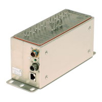
1. MPS4232 Module
2. Protecve Case
3. 155625 - Power Cable with Flying Leads
4. 156110 - Ethernet RJ45 Adaptor Cable
5. MPS4232 Resource Disk - USB (contains full calibra-
on report, rmware les, and backup coecients)
6. Cercate of Calibraon
The MPS can be mounted in any orientaon. The light-
weight nature of the MPS4232 allows it to be xed to a
surface using velcro or similar. Note: The screws on the
back side of the MPS should not be removed and used for
mounng. These screws maintain the leak-ght aspect of
the module.
The MPS4232 series scanner is designed to withstand
normal industrial, ight test, educaonal, wind tunnel or
similar applicaons. The module is not water proof and it
should be protected from any splash, spray, or mist. If any
moisture gets spilled or splashed on the MPS module, wipe
it dry immediately to prevent damage to the module.
The MPS module should not be mounted in a locaon
where it may be subjected to extreme temperature shis
or ambient temperatures outside limits dened in “Secon
1: Specicaons” on page 7. Keep in mind that the
internal temperature of the module will run approximately
5°C - 10°C warmer than ambient temperature. This temper-
ature increase is accounted for in the calibraon tables.
The temperature specicaon listed is in relaon to the
ambient temperature.
CAUTION! Mounng the MPS
module inadequately or in an envi-
ronment that does not conform to
the recommendaons can results in
permanent damage to the module.
Due to the design of the MPS4232, the accuracy is only
minimally impacted by the device warming up aer
inially being powered. The module can take up to 3 hours
to fully warm up (in a 25°C ambient environment). It is
recommended that the module be allowed to warm up
for a 15-30 minutes before collecng data, but this is not
mandatory. If me allows, the warm-up period should be
extended to 60 minutes for most applicaons.
The MPS module is designed primarily for Ethernet
communicaons. This provides a means to congure the
MPS module as well as scan and collect data from the
module.
A serial RS-232 connecon is also supported. The serial
connecon is designed to provide emergency commu-
nicaons with the module in cases where an Ethernet
connecon cannot be established. If the internal memory
in the MPS is corrupted in any way, the serial connecon
allows the user to format the memory and restore the
operang les.
Every MPS4232 module has an RS-232 serial output. It is
available through the Power/Serial/Trigger connector
on the module. This connector on the module is a TE
Connecvity PLG 8P8C Mini1. This is a latching connector
to prevent the connector from becoming unseated when
subjected to vibraons. The wiring diagram for the power/
serial/trigger connector can be found in Secon 4: Hard-
ware.
Sengs for establishing a serial connecon to the MPS4232
module are as follows:
Bits per second: 9600 BAUD
Data bits: 8
Parity: none
Stop bits: 1
Flow control: none
A serial and Ethernet connecon can be established simul-
taneously. All commands listed in Secon 5 are accepted
via serial communicaons.
The serial connecon is designed to be used to congure
the module, provide emergency communicaons for