29
MPS4232
Section 4: Hardware
The O-rings supported in the header cavity should be
kept clean and watched to make sure they stay in place.
Replacement or addional headers can be purchase sepa-
rately as needed.
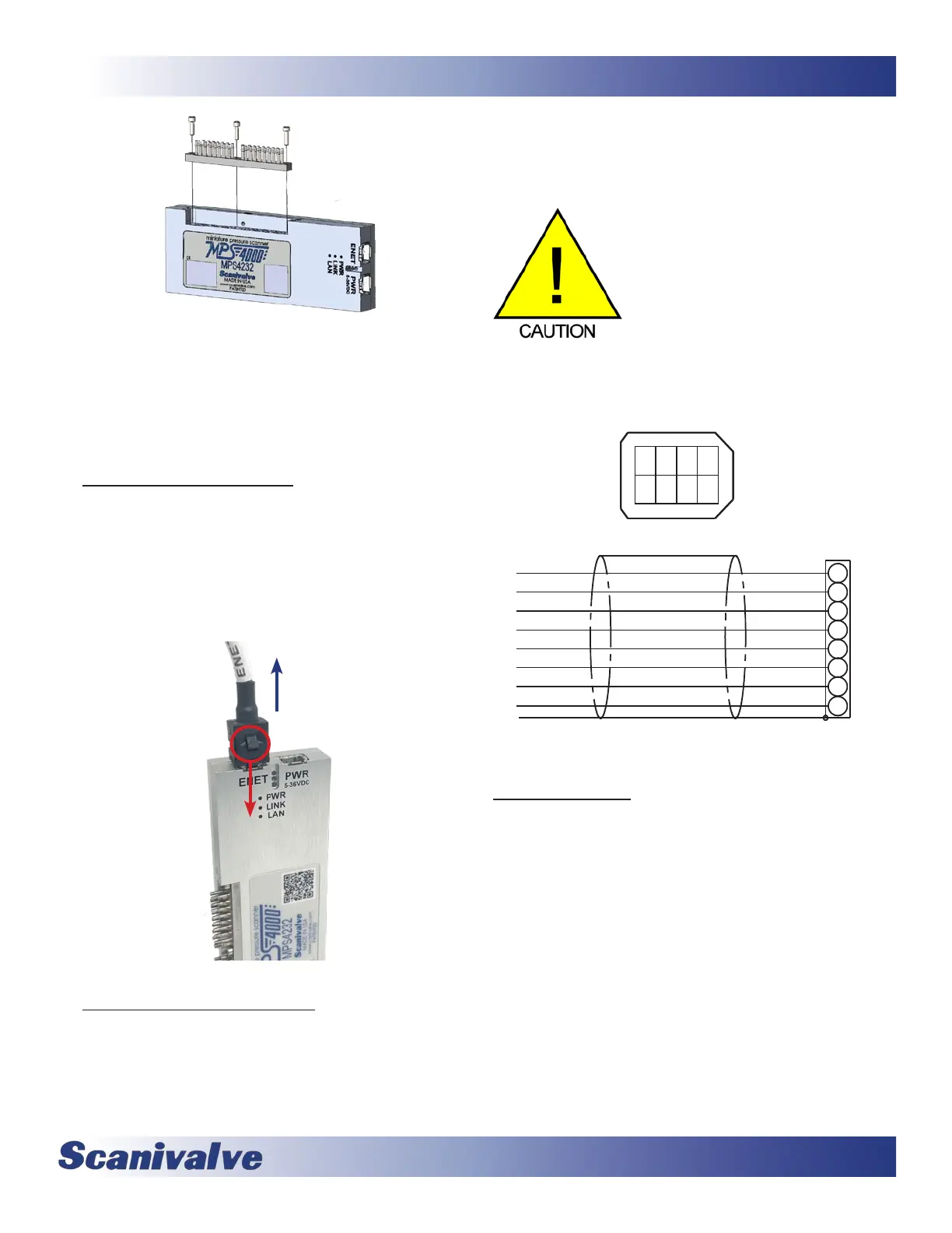
The MPS4232 has two electrical connectors located
adjacent to each other on one end of the module. Both
connectors are TE Connecvity “Mini I/O” series and are
polarized to prevent improper connecons. The connec-
tors are latching to ensure a reliable connecon. To
disconnect the connectors, press down on the latch (shown
in Figure 4-4 below) and pull up on the connector.
The power/serial/trigger connector is located on the end of
the module. The connector is an TE Connecvity PLG 8P8C
Mini1. A ying leads cable is provided with each shipped
MPS. The Pin-Out diagram for the power connector can be
found in Figure 4-5.
Addional cables for the MPS modules can be ordered
from Scanivalve in any length up to 100 feet (30 meters).
Please see the Module Accessory Catalog for dierent cable
opons and part numbers.
CAUTION! Do not make or break
the power connector with power
applied! Doing so risks damage to
the module.
The MPS4232 requires +5-36Vdc power and will consume
no more than 3.5W.
8
7
6
5
4
3
2
1
8
3
2
7
1
6
5
4
EULB
LEY
GIRT-
YRG
THW
DER
NRG
NRB
KLB
Serial RX
Serial TX
Serial GND
+T IR G
5-36 RTN
5-36 VIN
5-36 RTN
The primary means of communicaon with the MPS4232
module is the 100Base-T Ethernet port with MDIX auto-
crossing. The connector is an TE Connecvity PLG 8P8C
Mini1. A 3 Ethernet extender cable (female RJ45) is
provided with each shipped MPS. The Ethernet Pin-Out
diagram is shown in Figure 4-6.
Addional cables for the MPS modules can be ordered
from Scanivalve in any length up to 100 feet (30 meters).
Please see the Module Accessory Catalog for dierent cable
opons and part numbers.