14
MPS4232
Section 3: Operation
troubleshoong and nd/change the MPS’s IP address if
it is unknown. For informaon on changing the commu-
nicaon parameters, including the module’s Ethernet IP
address, see “Changing the IP Address” procedure.
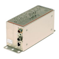
The Power/Serial/Trigger Communicaons port also serves
as the input for the power and external scan trigger
connecons. For more informaon on externally triggering
scans, see “Scanning With An External Trigger.”
Several power/serial/trigger cables are available for
purchase. Please see the Module Accessory Catalog for all
cabling opons.
The MPS4232 has one Ethernet 100Base-T with MDIX
auto-crossing connecon. This is the primary means
of communicaons with the MPS. This connector on
the module is a TE Connecvity PLG 8P8C Mini2. This
is a latching connector to prevent the connector from
becoming unseated when subjected to vibraons.
Shielded Category 5e cable or beer is recommended
for all Ethernet connecons. The wiring diagram for the
Ethernet connector can be found in Secon 4: Hardware.
Several Ethernet cables are available for purchase. Please
see the Module Accessory Catalog for all cabling opons.
Before an Ethernet connecon can be established, the IP
address must be congured. This can be done manually
with a “stac” IP address. If a “stac” IP address is desired,
the IP address of the MPS must be set manually. The IP
address assigned to the MPS must be compable
with the network/host computer.
If a stac IP address is desired, the IP address must be
manually congured. The IP address that is congured in
the MPS must be compable with the network the MPS is
being connected to. If simply connecng the MPS directly
to a host computer, the IP address of the MPS and the host
computer must be compable, which may require manual
conguraon of the MPS and/or computer.
The range of compable IP addresses is dened by
the subnet mask. The standard default subnet mask
is 255.255.0.0. This default subnet mask requires that
the IP address of the module and host computer must
share the rst two octets, or sets of numbers. The third
and fourth octets of the IP address are variable with this
subnet, although it is typically recommended that the third
octet also be shared between the host computer and the
module. The subnet mask digits of “255” dene that the
two IP addresses must have matching digits in those posi-
ons, and the subnet mask digit of “0” allows the two IP
addresses to have unique values for those octets and sll
be compable. No two devices on a single network can
share the same IP address. Below are some examples of
compable and non-compable IP addresses:
Example of matching the rst three octets
Subnet mask: 255.255.255.0
Host computer: 191.30.95.90
MPS module: 191.30.95.100
Example of matching the rst two octets
Subnet mask: 255.255.0.0
Host computer: 191.30.1.1
MPS module: 191.30.95.125
Example of NON-COMPATIBLE IP addresses
Subnet mask: 255.255.255.0
Host computer: 191.30.1.1
MPS module: 191.30.95.5
When conguring the network, the IP address of the MPS
module can be modied to match the network, or the
IP address of the host computer can be modied to be
compable with the MPS module.
The IP address of a Windows 7, 8, or 10 host computer can
be changed under:
Control Panel -> Network and Sharing Center -> Local
Area Connecon/Ethernet -> Properes -> Internet
Protocol Version 4 (TCP/IPv4) -> Properes
Changing the IP address of the host computer may require
administrave rights.
The IP address of the computer can quickly be found using
Windows Command Prompt and the command “ipcong.”
MPS4200 modules are shipped with a pre-congured IP
address that uses the following format:
191.30.95.xxx
The rst two octets used are unique to all Scanivalve prod-
ucts (191.30). The third octet is the device family code (95
for MPS4232). The fourth octet is the last three digits of
the MPS’s serial number. “xxx” is only a placeholder in the
example as all modules will have dierent serial numbers.
Based on the examples above, the host computer can be
congured to communicate with the shipped IP address of
an MPS.
In situaons where the IP address of the host computer